Creating a simple monopole antenna for your FPV video transmitter have various advantages over more complicated and heavier circular polarized antennas. This tutorial will guide you through the process of making a simple monopole antenna for a 5.8Ghz FPV system, which is particularly useful for applications where weight is a critical factor, like micro quadcopters.

Linear polarized antenna is a type of FPV antenna, and it can be made very small and light weight, especially useful for weight-critical application, such as on a micro quadcopter.
Table of Contents
Understanding Dipole Antenna
There are two main types of linearly polarized antennas used in FPV, monopole and dipole antennas.
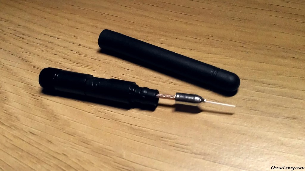
A dipole antenna you find in most 5.8Ghz video transmitters or receivers is essentially a coaxial cable. The key aspect to focus on is the length of the exposed wire (the part without shielding), as it directly affects the signal frequency it receives. For instance, a wire length of about 12.92mm is tuned for 5.8Ghz, while a slightly shorter length, like 12.70mm, tunes it to 5.9Ghz.


Understanding Monopole Antenna
Monopole antennas are simply a piece of wire without ground planes. Many built-in receivers in flight controllers use this type of antenna to minimize footprint and weight.

Materials Needed
For building a dipole antenna with ground plane, you will need a proper coaxial cable (options include RG316, RG178, or other thin antenna cables)
- RG316: https://amzn.to/3S8FG0B
- RG178: https://amzn.to/48LnDTA
You might also need a SMA connector (https://bit.ly/41Qxk11) depending on your setup.
For building a monopole antenna, then simply use any electrical wires, usually work fine for RC purposes.
Building the Antenna
- Selecting the Coaxial Cable: Choose a coaxial cable based on your needs. RG316 and RG178 are popular choices, with the former being thicker and offering better shielding. For lightweight applications, thinner cables like RX replacement cables are suitable.
- Calculating the Wire Length: The length of your monopole antenna should be a quarter of the signal’s wavelength. You can calculate this using the formula:
Length (m) = c / frequency / 4
where is the speed of light (approximately 3×10⁸ meters/second).
For a 5.8Ghz FPV system, the calculation would be:
Length (m)=3×1085.8×109×14
- Cutting the Cable: Measure and cut the coaxial cable to the calculated length for the exposed part. The rest of the cable, with shielding, can be of any length that suits your setup.
- Attaching the Connector: If your setup requires an SMA connector, solder the cut coaxial cable to the connector. Ensure a solid and clean soldering job for the best signal quality.
- Direct Soldering (Optional): If you choose to solder the antenna directly to the video transmitter, skip the SMA connector and solder the coax cable’s exposed end directly to the transmitter’s antenna pad.

Further reading: 5.8Ghz Frequency Bands For different FPV brands.
31 comments
If I use a length of bare, copper wire – would I need it to be shielded in some way? I’ve been using a 4-in length of copper wire in its original jacket, and leaving 31.2 mm of bare wire exposed at the end. The jacketed end is soldered, directly, to the video card.
Also, if I had to shield that wire, how would I connect the shielding to the video card solder joint?
Hi, there is no metallic shield on the wire you describe. If making a monopole antenna as described then your wire counts for its entire length regardless of stripped insulation. You should adjust your length accordingly.
Alternatively you could make a dipole antenna out of coaxial cable following the other set of instructions in the article.
Hello
Excellent piece if info ,
One query
Does the thickness of the coax between the antenna and receiver matter ? As Rg 316 , 178 has been suggested, could you use RG 5 or RG 6 for extension purposes ?
Regards
Other than size and ease of placing on a build, what are the situations where you would want to use a small dipole instead of a CP antenna? Wondering becasue of the Emax Magnum I just purchase has the option for both. I will primarily use that quad for racing and within 200 yds (175 meters) of distance.
In the case of say an Echine Aurora 100 for example – crash survival being a higher priority than range, possibly. It’s why I’m here anyway.
could this work in reverse also? measure your whip antenna and the choose the best channel for your antenna?
(299792458 / 4) / length = best Channel
I have a question, why /4?
To keep the transmitter happy with the antennas impedance. A full wavelength is fine, and any 1/4 of that. But, we use 1/4 as a standard because it is short and still allows slight gain. There are other lengths that work equally as well, but need matching circuits to keep the transmitter from burning out. 1/4 is just the simplest length we use.
What is that little cylinder metal shape is on the top of the antenna?
What is the purpose of having it?
Thanks
it’s a crystal, critical part of the camera.
Haha Tim.
They are both “radio” frequencies
>>If you are using Coaxial Cable, it doesn’t matter how long the shell is, all that matter is the exposed wire (the part that is without the shielding).
I’m not so sure of that. Coax simply help to not emit but I have forgot how it works exactly (I studied that a long long time ago but even with coaxial cable you may have to take in accounts length to open the wires from the coax to antenna where the signal is the strongest because of standing waves. Maybe this can helps for those who understand : solar.fc.ul.pt/lafspapers/coaxial.pdf , so as a rule of thumb, a cable cut at n times waves length is better than a random cut, and you have to take in account the celerity into the coax (2/3 usually). To be verified by somebody who has studied wave propagation more recently than me.
You are mostly correct. After 35 years in broadcasting, I can definitely say the length of the shield portion is DEFINITELY important. I would just say go the other way though. Avoid any length that is resonant. Random lengths that don’t equate to a 1/4 wavelength (or 1/2, 3/4, 1 etc) won;t be a problem.
With the short wavelengths 5.8 uses, it’s pretty easy to hit one if you just use a random length.
hello.
I fly on 5733 mhz . Speedof light is 299792458 m/s .
299792458/5733/4= 13.073,105616605
my wire length is 13.073 mm ??
yes :)
Good stuff, rigged one up in less than 5 min.
Hey Oscar !!!
Thanks for this I love the simplicity of the single copper antenna on my whoop. Yesterday I broke my vx1100 cloverleaf and cut one of the leafs down to 12.92mm and soldered it back on to the center pin of where the other one was and voila !!! reception… cant really tell but I think its better than before. don’t really expect much from the 10mw cam but it works well enough for cruzin’ around the house and I didn’t have to buy another !!!
is 12.92 the magic number for 5.8 or is there another resource I should refer to as I fall down this rabbit hole ???
Thanks again and Cheers !!!
~Kirk
12.92mm or +/-0.2mm depends on the actually frequency you use :) But 12.92 works just fine.
The Taranis and the others you mentioned are for 2.4Ghz. Oscar’s blog post is right on the money for a 5.8ghz antenna. The picture shown is a sleeved dipole not a regular dipole. The sleeved dipole has a ground plance “bullet” of the same length as the exposed wire. I’ve had really good results with a basic dipole – exposed wire around 12.9mm length. The speed of signal is slower in the wire than in the air hence the very small discrepancy in the calculated 1/4 wavelength and the length of the wire.
So to recap – 2.4Ghz uses a long wire for 1/4 wavelength based on the frequency calculation.
For 5.8Ghz video the exposed wire length = ~12.9mm
The simple cobber antenna in your picture. What lenght is that. I find it hard to understand the way you explain “bare” wire lenght og a whip antenna. There is no bare exept at the very bottom where antenna ond two negative wires stick out. The simple splutioon with jus one cobber cable seems more easy and if it works as godd I’ll use it. Building a H8 mikro indoor surprise for the son. Like this one: youtube.com/watch?v=DREHnDY1WVk
Please search for “length” in the article you will find the number. “bare” is basically the exposed wire without shielding.
The bullet shaped piece is not plastic, it’s metal and serves as a counterpoise. It and the exposed center conductor together make a dipole antenna.
Hi Oscar, what is the bullet shaped piece of metal for?
it’s plastic, i think it’s just to protect the shield casing.
That metal bullet shaped piece is a counterpoise for the antenna. It’s similar in operation to a ground plane on other antennas. It basically balances the antenna and makes it a certified dipole.
The antenna is shorter on some due to the velocity factor of the coax cable. 11.71 is likely correct when tuned to match the cable.
If I search the web for 5.8 linear antenna length I get very different results. You saying here the correct length should be 12.92 mm. On rcgroups some folks are saying 2.3 and 2.7mm. wtf? So what is the right length?
everywhere I have seen suggests around 13mm, and I have been using that in my DIY antenna and getting decent results..
if you measure any existing commercial antenna you should also they use this length…
lastly, i would really appreciate it if you could join the forum: http://intoFPV.com … I don’t want to miss your comment, because I only check my blog comments only once a week, but I use the forum daily!
I guess it’s better to calculate the wavelangth as ”Length (m) = (c / frequency ) / (4 x 0.93)”
The velocity of electricity in copper will effect the lengt of the antenna.
(Sry for my english)
i’ve been searching everywhere for this! wouldn’t that make it slightly shorter? i’m trying to figure out why the taranis and other 3rd party replacement antennas i’ve bought are around 32.5mm instead of 31.2mm?
Taranis is 2.4GHz radio.
FPV is 5.8GHz video.