
I got this RCbenchmark 1520 thrust stand to replace the Turnigy thrust stand I have been using for my motor, ESC and propeller testing. Here is a quick comparison and review.

Here is a list of tools you should get for building/flying mini quads.
The 1520 series thrust stand is made by RCBenchMark.com. For the rest of the article I will refer to this stand as RCBM. It’s also available at Hobbyking if shipping is easier for you.
Two Stand Models – RCbenchmark 1520 vs 1580
There are 2 thrust stand models from RCbenchmark. The basic 1520 is priced at $165, while the more advanced 1580 is $495!
The 1580 does a lot more like measuring motor torque, vibration (detects motor/prop balance), temperature, motor wilding resistance etc. I think the 1580 is more for R&D, for our hobbyists I think the 1520 would suffice.
For a more detail differences check out their comparison table.
Note that there is no upgrade kit for the 1520 to 1580, so make your decision carefully. Since I have the 1520 I will focus on this model for the rest of the article.
Comparing to the Turnigy Thrust Stand
The more affordable Turnigy Thrust stands are standalone solutions with built-in LCD screen, pretty nice if you just want to quickly test a motor/prop and ESC combo. The Turnigy V2 even has a power analyser (power meter) that measures the voltage, current and wattage. Although the RCBenchMark stands also has power meter, it doesn’t have any servo tester knob or LCD display built-in. Therefore it requires connection to a computer to control the motor and to read the values.
However the RCBM stand has better thrust precision than the Turnigy. As an owner of a Turnigy stand, I am not confident with the accuracy of the results. Often times after a test the scale doesn’t even return to 0.
The RCBM also has a built-in electrical RPM probe (rotation per minute), as well as being capable of running powerful automation scripts for your tests.
Side by side comparison with my Turnigy thrust stand.

To sum up the advantages of the RCBM thrust stand:
- Built-in power meter (up to 35V, 40A current)
- More accurate data
- Direct measurement and continuos data logging (in a spreadsheet)
- Measures motor RPM
- Manual control as well as automation scripts (for large scale standard tests)
- Light weight and small (less than 300g)
- The scale works both way: push and pull (range of -5Kg to 5Kg)
- Integrated ESC signal controller (no additional servo tester required), but you can so use external servo tester
- High sampling frequency – The load cell refreshes at a constant rate of 8Hz
- Ability to perform calibration is very important to ensure test result consistency
Disadvantages or things I think they can improve on
- No heavy flat base, therefore it requires additional clamps or mounting bolts already installed on a workbench
- No physical control or LCD screen built-in, and it have to be connected to a computer in order to use it (wireless option isn’t available so cable is required)
- Expensive (but you get what you pay for)
- Only support up to 40A of current – although it’s pretty much enough for what we test right now, but it’s hard to say RC multirotor motors won’t evolve and exceed this limit in the future
- ESC control signal is only standard PWM – maybe they can impletement Oneshot or even Multishot in the future (although you could use external ESC signal from a flight controller for now)
Unboxing and Assembly
What’s included

From top left to bottom right:
- bolts, washers, 2 Allen hex wrench and a few zip ties
- thrust stand lower structure and 2 motor mounts
- a mini USB cable (15 feet long)
- a measurement circuit (controller board)
- 2x power cable (2.5 feet) and wires for RPM probe
- a load cell
Here is the controller board (measurement circuit) close-ups.


It comes with 2 motor mounts for different motor sizes, and the manual which is also available here in PDF format.


Here we begin to put the thrust stand together following the instructions. Note that the load cell is rated for 5Kg, which is more than enough for most RC hobbyists. For us mini quad flyers, even the most powerful motors only generate under 2Kg thrust (normally) so we should be fine.


Installing the motor mount on the load cell.

And installing the power cable on the control board’s screw terminals. I love using screw terminals as they are soldering-free, i have been using them on my ESC’s to motor connection also when I am doing thrust tests.
The power cables are 12AWG, 2.5 feet long.

Now since the RCBM thrust stand has been assembled, we can now install our ESC and motor. There is a dedicated area where you are supposed to mount your ESC on with double sided tape or zip tie. You can simply insert the ESC power wires into the screw terminals.

And here is the motor mounted on the stand.

To measure electrical RPM, we need to connect a wire to one of the 3 motor phases. We are provided with wires to do that, they even pre-stripped the end for us, how thoughtful! :)


And finally the stand needs to be mounted on a table with Clamps. Mine are still on delivery, that’s why I can’t test the stand yet.

After assembly, connect the stand to PC and perform load-cell calibration per instruction manual.
Software
GUI can be found in Chrome web store (extension), by searching “RCbenchmark”. The stand was plug and play for me. Right after the stand was plugged in, the GUI detects the firmware, and I was warned about the outdated firmware. Firmware update was just one click away.
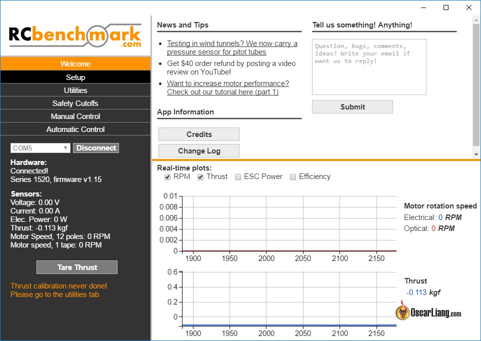
Here is the home tab of the GUI (Welcome).
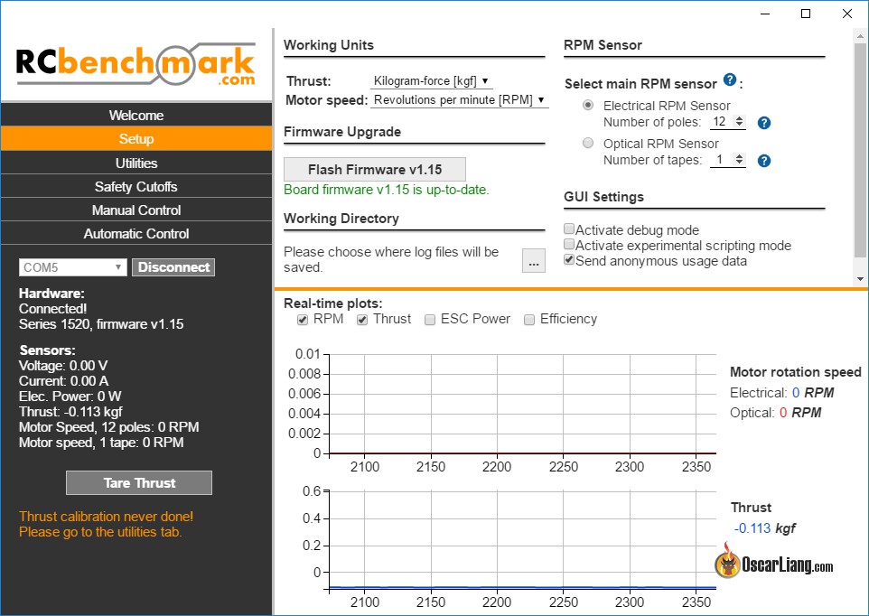
Here is the Setup tab, where you can configure basic settings you want to work with, like units, log files saving directory, RPM sensor and GUI settings etc.
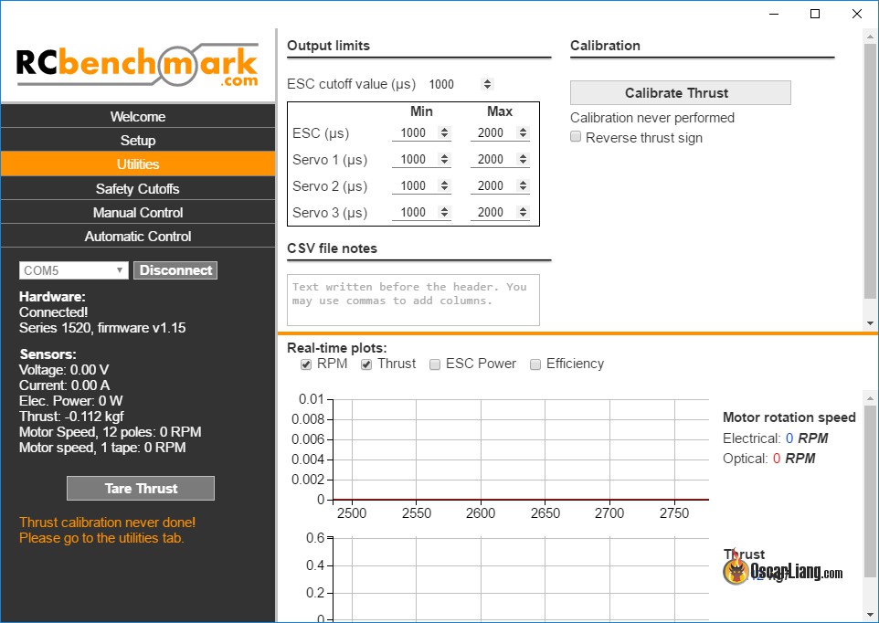
Utilities tab allows you to set limit to ESC signal, and to perform thrust calibration.
Safety Cutoffs tab allows you to set limits on power supply, as well as max thrust.

Manual Control tab is probably the tab we will be using the most. It’s pretty much like the motor tab in Cleanflight where you can send a ESC signal out (PWM) by sliding the thing up and down. While controlling the motor, you can take measurement sample, or start logging data in a CSV file.

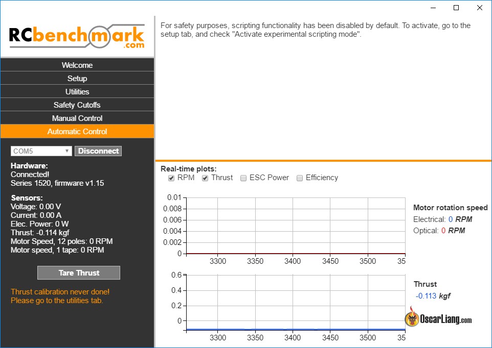
This tab is the beauty of this thrust stand IMO, where you can execute automation test scripts. Scripts are a great time saver for testing a large mount of samples, and it ensure the identical procedure are repeated.
A word of warning, Google is shutting down Chrome App in 2018, which means the GUI software for the RCBenchMark Thrust Stand will be made unavailable (as well as Cleanflight Configurator!). However I believe RCBM is already working on an alternative solution.
Measuring RPM with Optical Sensor
The RCbenchmark Series 1520 and 1580 already come with an electrical RPM probe. This electrical probe connects to one of the motor phases signal to extract the motor rotation speed. In most cases it works very well, but for very low KV motors, and brushed motors you can optionally use this optical probe.

Conclusion
It’s twice as expensive as the Turnigy Thrust Stand, but if you are serious about this hobby I think it’s worth the extra cost. Hardware wise there aren’t too much to it, but the stand is really well designed, and build quality is top notch. You are also receiving support directly from the company. The software is also excellent and does data logging and many other cool things.
I really wish they could make an add-on for servo tester knob, and LCD screen that turns it into a standalone thrust stand. It would allow the users to perform quick tests without a computer, and great for situations where connection to a computer isn’t possible.
I will come back and update when I am more experienced with the product.
6 comments
How is this device measuring RPM?
One thing I think might be overlooked some, is how reactive a prop may be. For example, prop A can go from 0 to 1k thrust in X seconds. Prop B does it in Y seconds. I think this would be more important to Acro flyers, as it would make flips and such more reactive.
Hi,
I´m totally with Mike … I´ve the 1580 stand, mounted on my working bench. I installed a plexiglass wand that saves me from breaking propellers and parts which can happen (and happened) at full throttle testing. Using a cheap Win10-Tablet/Subnote behind it to run scripted tests, which are fast, easy, highly accurate and reproducable.
Want to add, that service from RCB is perfect! They are enthusiastic professionals and give answers and their thoughts to almost any question. Simply great :-)
Hopefully you can run your tests soon, Oscar. It is fun all the time and I´m very interested in your experiences/results also.
cheers: Oliver
I have one of these excellent stands and it is a vast improvement compared to the inaccurate Turnigy thrust stands.
Some of the things you raise as negatives are, I feel, only negatives because you have not actually used the stand yet. I’d like to comment on some of those points:
“No heavy flat base, therefore it requires additional clamps or mounting bolts already installed on a workbench”
Although the Turnigy stand might have a flat base, it’s hardly heavy and it also needs bolting or clamping to a solid support. This is a much safer way to work than attempting to hold the stand still with your hand right next to a motor that could be running at full speed. A base that was heavy enough not to move with 2Kg+ of thrust acting on it would be so heavy that shipping would cost more than the device!
“No physical control or LCD screen built-in, and it have to be connected to a computer in order to use it (wireless option isn’t available so cable is required)”
You are missing the point here. The whole idea with the stand is that it is computer controlled. You can accurately log RPM, Thrust, voltage and current to your PC without having to manually observe these values. As the ESC signal is also computer generated, setting the output to 1750 (for example) will give you exactly what you ask for which is something you would be hard pushed to do accurately with a simple dial. Although there are manual controls, I never use them. A simple script that sets the throttle to various levels and logs the results at each throttle level is the way to go. Thrust testing is then a simple matter of starting the test and automatically logging the data as the test runs. There is always a risk, when running a motor at full power, that a propeller might break. Automated testing allows you to retreat to a safe distance while testing is being performed. Much safer and above all, accurate and repeatable.
“ESC control signal is only standard PWM”
This is truly irrelevant. Faster ESC communication is only a factor during flight where throttle levels need to change very quickly to be as close as possible to what the flight controller’s PID loop wants right now. In a static thrust test, this does not matter and as long as you have calibrated the ESC against the stand’s PWM signal, full throttle will run the motor at maximum power regardless of if full throttle is represented by a 2000 microsecond pulse or a 125 microsecond pulse.
I hope that we don’t see motors that will pull more than 40A each. Even with the best batteries available, supplying over 160A to a quad is very hard to achieve and getting any kind of useful flight time from such a monster would be difficult to say the least!
thanks for the long comment :) to your questions
1. I said that because i like the convenience provided by the Turnigy stands, as long as you can keep it from sliding, it doesn’t requires bolts or clamps to hold it in place.
2. I guess you didn’t read the whole review :) Computer control is great :) but there are times we just want some quick result and a LCD screen would be great for that. It doesn’t have to replace the existing system, perhaps an add-on would be great :)
3. the signal does make a difference when testing ESC and motor. I don’t know how much as i haven’t done a comparison myself, but at least this will be able to show problems with different ESC protocols prior to testing them on a quad :) that would be useful wouldn’t it :)
4. There are already motors/prop combo that can pull 40A actually :) it’s just we don’t use them on quads yet as it’s not practical :) but never say never :)
Great article. Thanks