In this quick post, we will explore the different ways of turning on and off LEDs on your quadcopter or multicopter, using your radio RC transmitter.
Why do we add LED (or LED strip) to our multicopters?
- It helps us identify pilots in FPV race
- It helps us find the crashed quadcopter easily
- A good warning for bypassers on the ground
- Importantly, it looks awesome! Especially at night
LED lights don’t use much power (almost negligible compared to what the motors use! :D ). It’s good to have the LED on, but sometimes you want to turn the LED off remotely while flying, because you are too lazy to land. How do we do that? We can use our AUX switch on RC transmitter!
There are a few solutions to this, and I found some really cool demonstrations on Youtube. However it’s not a full list so please let me know if you know other good implementations.
All these methods require you to have at least one spare channel on the radio receiver, and you are not running CPPM.
Get CleanFlight on Naze32
CleanFlight has this awesome feature that supports RGB LEDs to change colour, depending on flight modes, voltage warning, orientation, etc. Here is how I setup the LEDs with Cleanflight on my Naze32 flight controller.
And here is a quick demo.
https://www.youtube.com/watch?v=ZxCfP580f0o
Using receiver controlled switch (Transmitter PWM On Off Switch)
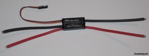
This is the simplest solution. This on off switch works straight out of the box, it is controlled by a channel of the RC transmitter radio.
Here is an example of the kind of switch. Minimum amount of DIY work and soldering. There are 3 wires come out of this switch. The signal wire goes into the spare radio receiver channel, one of the red wire connects to the positive end of the LED strip, the other one connects to the positive end of your battery (or power source).
Using Old Servo Board PCB
Apart from a ready made receiver controlled switch, you can also hack a old servo, and turn it into something useful.
All you really need is the PCB from the servo, plus the pot. But you can replace the pot with a couple of resistors. It takes a PWM signal from the receiver, and the PCB will adjust the voltage at the output.
Set the output arm/pot at neutral and they will turn on when you put the switch one way.
Only problem might be the voltage you are allowed to apply on it, and the maximum current that is allowed to pass. Most 9g servo can only handle 5v and run a current around 200mah.
To tackle that, you can consider driving a transistor switch circuit for higher voltage and current (e.g. 12v).
With the Servo PCB you can even create a diming effect on the LEDs.
Here is a good tutorial on how to make on step by step.
Brushed ESC
Alternatively you can use an ESC to replace the on-off swtich. But it has to be a brushed ESC, not a brushless ESC (which is 3-phase). It’s not a lot cheaper nor easier than the receiver controlled switch, but if you have one available you can try it.
Microcontroller chip
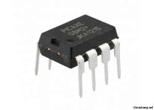
This might seem to be a bit overkilled, but if you are a DIY geek, it could be a fun challenging project. There are many affordable microcontroller you can use, such as the PICAXE, Arduino.
For example the PICAXE can be used to switch LED lights on and off, and even to generate the flashes or different lighting patterns. The PICAXE chip can be programmed direct from a PC using free software, and is programmed in BASIC. It runs off up to 5v, but with the addition of transistors in the output stage, can be configured to switch practically any voltage and amps.


24 comments
How can I turn off and on LED lights from my R-XSR and flight controller from an AUX channel if I have a Taranis X9D transmitter? Most receiver switches require a servo connection which the R-XSR does not have.
I have an electronic switch that will control leds on,off,flashing depending on the toggle of the servo channel. But I just want them to go on when I lower the retracts, that means I need to cycle the receiver channel on/off 3 times. Is there a way of doing this? maybe using the logical switch timer?
Hi Oscar, great website by the way. What about just a servo pushing/pulling a simple mechanical switch or micro switch? Just a thought, hope it’s a helpful thought :-)
That’s over complicating things a little don’t you think :)
Hi,
I know this post is from a while ago. But hopefully somebody can still help me out.
I have build a race quad with a Kiss FC and an FRsky X4R . I’m not sure if you are familiar with this equipment.
I want to make a hot burning (steel) wire (to make fireworks go off on command).
The problem I have is that I run Sbus, so i cannot control different channels just by plugging in some cables to the receiver. (unless there is a way to connect Sbus and cppm at the same time, there are 3 channels left on my receiver).
I tried many things, such as the buzzer connection, to make a short circuit. I also bought the polulu rc switch, because i first thought that the aux on the flight controller was the same aux that i would use in the software.
kiss.flyduino.net/kiss-fc-flightcontroller/
frsky-rc.com/download/view.php?sort=&down=158&file=X4R-X4RSB
pololu.com/product/2803
I really hope somebody can help me out!
Thanks
I built a library which takes two PWM inputs and transform them into two outputs (also PWM). The library uses an Atmel ATTiny85, and also features an auto-calibration system in order to adjust the outputs as wanted.
If anyone want to use it, it can be found on GitHub here: github.com/Atom058/AtmelRC
Hi Oscar
A much smaller solution is to use one of pololu’s tiny rc switches
pololu.com/product/2802 and https://www.pololu.com/product/2803
I use the 3A ones in my mini quads they are very small.light and cheep.
Hi Oscar, Do you think if i enable servo tilt in cleanflight, could I use one of the servo outputs to control my pwm receiver controlled switch? or could the buzzer output on the flip 32 switch the pwm switch? im worried about damaging the board.
servo output from FC should be fine.. shouldn’t damage your FC.
Thanks Oscar, It works. I used the Pan output and mapped a switch on the taranis. Switching 100 Watt LED load. Have the tilt hooked up to the FPV cam with 3 positions on a switch.
You have really become THE Quadcopter GURU !
Hi Oscar,
Thanks for the instructions on switching LEDs by a recycled servo. It is exactly what I need.
My LEDs are 12V – could I add a DC-DC step-up module after the servo (derived) switch?
Or is the output from the switch -5V to +5V, which might upset the step-up module?
Or, whatever the output from the switch, it won’t matter because the LED’s will not allow current to flow “in the other direction”?
Sorry for my layman’s questions.
Thanks in advance,
Stefan
Hi,
is it possible to use a Naze32 (with CleanFlight) PWM output to turn on/off the LEDs? I’m using FrSky D4R-II receiver in PPM mode, so I don’t have a (free) PWM output on it.
Not really unless Cleanflight write some code for this function. The best I can think of is you can add a switch to the power of LEDs, which you can turn it on and off manually.
Thanks your blog is really informative.
I have 6 ch and i am using 4 ch i want to control a camera from ch5 or ch6 for recording, pause etc. Is it possible to hook a digital camera with my receiver?
Thanks
It should be possible, but you will need some DIY work, either digital, or mechanical system to make the camera do that… I have not done this so i cannot advice much.
Yes exactly. I am using a CC3D which I don’t believe is able to connect a alarm/buzzer. It is for a ZMR250 that has a custom PDB bottom plate. (overcraft if you are familiar with it). The PDB has a buzzer soldered on it and pos and neg pads which can be wired to a Naze FC. Since the CC3D doesn’t have that capability, I was trying to figure a work around that didn’t include the FC.
I see, yea, try the receiver switch trick. I haven’t tried it, but it seems doable. :)
Thanks Oscar you’re very helpful and your blog is a great thing.
Have you noticed that the security math question you have to answer each time before you post gets more and more difficult the more you post. Glad this is my last question on this subject, as now we are in multiplication, and if it moves to fractions or anything else I’d be lost. Haha
LOL The maths question is a good brain exercise :)
Thanks for the kind words! :D
Hi! Did you figure it out? I’m in the same position as you and I’m going crazy at the moment trying to make it work.
Cheers!
Oscar is the receiver controlled switch basically an on/off switch? I’m wondering why the signal wire connecting to the receiver is needed. The reason I ask is I have a PDB that has a built in buzzer with a + and – solder pad which in layman’s terms is an extension of the + and – pins that come out the bottom of the buzzer and are soldered to the board. There is no power to the buzzer yet.
If I were to set up the receiver controlled switch as you described, but instead of connecting 1 red wire from the switch to the LED strip, connect it to the positive pad on the PDB for the buzzer and connect the other red to power and run a wire from the – pad and connect to a ground, would the buzzer work and be able to be turned on/off from a programed switch on the radio?
yes it is. if you don’t have any input to the switch, how do you control the switch from your transmitter? sorry i don’t really understand the second part of your comment.
Thanks Oscar. Sorry for the confusion on my question. I have a lot to learn. I guess what I am asking is if I were to use a buzzer in place of the LEDs in your above example, would I be able to turn the buzzer on and off via a switch on the radio? Thank you
No worries Mike, to your question, Yes you can :)
are you trying to make something like a lost plane alarm?
some flight controllers have this feature built-in actually.