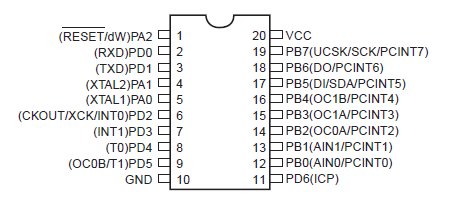
To read a voltage we usually need analogue input. Unfortunately, the ATtiny4313 doesn’t have any analog input, which could have made reading voltage so much simpler. I was almost giving up on this feature, until I realize there are analogue comparator on the ATTiny4313 and 2313, which I could use for simple voltage level checking. The comparator in the ATtiny2313 is used to compare a changing voltage with a fixed reference voltage. The comparator pins are 13 (AIN0) and 14 (AIN1).


Here is how I do it: I connect “changing voltage pin” to the battery, and the “fixed reference voltage pin” to a voltages such as 3.7V. I can then compare the battery voltage and reference voltage. To get a relatively accurate battery voltage, we need run the compare several times with multiple reference voltages, such as 4.0V, 3.7V, 3.4V etc. So we know at which range the battery voltage is at.
How to Get Fixed Reference Voltages
You might be wondering where do I get the 4.2V, 3.7V etc, since there is no analog pins. Well, you could use potential dividers to create these voltages, but it would be very difficult to change the voltage it creates, since the resistors are soldered on the board. Also it takes up a lot of space on the board if you have more reference voltages you want to use.
A better solution here would be using the PWM signal. Basically, PWM is a modulation technique that conforms the width of the pulse, formally the pulse duration, based on modulator signal information. There is concern about the “digital” property of this voltage because it goes up and down from 5V to 0V, which is not a smooth and constant voltage. To get smooth voltage we can use a low pass filter, which is essentially just consists of a 4.7 Kohm resistor and a 1 uF capacitor (see below circuit diagram). Because the capacitor takes time to charge and discharge between the change of voltage (or PWM pulse width), it’s important to delay long enough between “analogWrite()” and taking measurement of the voltage.

After comparing the battery voltage with a series of reference voltages, we can find the range of the Lipo battery voltage. The level of precision here depends on how many times you compare.
Basic ATTiny4313 and ATTiny2313 analog comparator Source Code
Here is an example how this comparator works. The use of Analog comparator in ATTiny4313 and 2313 involves direct access to some register, which does not need to declare by the user, such as the ACSR and ACO. Here is a good tutorial on how to use the comparator in action.
if (ACSR & (1 << ACO)) { //comparator output is high // Pin13 > Pin14 } else { // comparator output low // Pin13 <= Pin14 } Full Source Code I used to Determine Lipo Battery Voltage level
coming soon
3 comments
@Bart
The attiny45/85 has a full blown ADC. Just use that :)
Nowhere near fast enough for some use cases. The ADC is (a) noisy and (b) treacherously slow, in the order of milliseconds as I recall. Rather than mucking around waiting for a voltage level to pass a threshhold in a loop (which is time consuming and wasteful) you can use an interrupt and just get notified when or even if, that happens.
Hi, can’t wait for the source to test it myself. Good finding!
Would it also work with a attiny45 /85 ? also look at the forum – electronics where they try to create a wireless pir sensor alarm. A batt status is missing ;)