
In this project I implemented OpenCV color recognition on the Raspberry Pi that uses PID to control the pan-tilt servo system. In this post, I will explain briefly how color tracking works, and how to use PID control algorithm to improve tracking performance. Like my previous face recognition tutorial, I will be using the Wall-E robot in this Raspberry Pi Color Tracking project as an example.


The Raspberry Pi has relatively small computational capacity compared to a laptop or PC. Because of that you might notice the sluggish result in face recognition. But in color tracking, the result is quite smooth and satisfactory because the computational process is not as complex as face recognition.
We can use Raspberry Pi to control the servos directly using interface like ServoBlaster. But instead, I use the Arduino as a servo controller. Not only it’s easier to manage, but also there is PID library already available as a library on Arduino.
So this is how it works: the Raspberry Pi detects the color, work out the coordinates and send to the Arduino via I2C. The Arduino will then feed the data to the PID controller to calculate how much and to which direction to turn the servos.

What is PID and How to Use It?
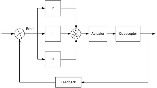
PID is a closed loop control system that is trying to minimize the error. In simple words, it takes the inputs from your sensor, and you tell it what your target set-point is, and it will come up with a output adjustment which aims to help your system to get closer to the set-point.
The most important factor of a optimal PID controller is its three constant parameters. To achieve good performance, we need to play around with different values to see different results. I will also talk about some tuning practices that I found helpful.
How to Use Arduino PID Controller
Using PID on Arduino is very easy, simply follow the instructions on this page to setup the library and we are good to go!
Following the examples provided in the library, its not hard to see how to use it. Basically, we need to:
- include the library
#include <PID_v1.h>
- define the necessary variables
double Setpoint, Input, Output;
- Construct the PID controller and establish links with the variables, specify the tuning constants
PID myPID(&Input, &Output, &Setpoint, 0.4, 0.4, 0, DIRECT);
- Measure input and feed into the PID controller, and retrieve output
Input = meansurement; myPID.Compute(); Adjustment = Output;
Tips on Tuning the PID constants
Depending on how you are using the output to adjust your system, the PID constants parameters will be different, so make sure have settled down on that before you start tuning. Sometimes not all three constants are needed (can be zero), it’s all down to your requirements and performance. If you don’t think some of the constants are helping, then set it to zero.
To start with, I usually set all PID constant parameters to 0, and then tune each constant in order, then randomly fine tune each one.
P (proportional), the key here is to get a quick strong response without any shake or vibration. From a small number and work your way up. The error rate at this point will be high and final accurate leveling will be slow. When this is set too high you will produce a high speed shake.
I (integral). The Integral algorithm will add more and more to the corrective action. This can help to balance inherent inconsistencies to the system, smoothing out errors over time. When this is set too high it will produce a slow wobble or oscillation (overshoot?), when it’s set too low errors will occur (damping effect?).
D (derivative). This parameter can have positive effect on overall stability of a mechanical system, i.e. it helps to overcome the inertia faster, etc.
Raspberry Pi Color Tracking and Source Code
Color Tracking using OpenCV is really simple, We basically need to go through this steps on the Raspberry Pi every time.
- Capture Image
- Throw away the pixels which are not falling in the range and high-light the pixel which are in the range, so you will see a black image with white dots and puddles.
- When the detected color has a large enough area, calculate the center position of that color using image moments.
- Send the position off to.
In the source code, we can choose whatever color you want to track. Look for the InRangeS() function. It takes source, lower bound color, upper bound color and destination. Just replace the lower bound and upper bound colors with the HSV values.
You can find this value of your favorite color using Gimp or MS Paint. Note that software like Gimp and MS paint use Hue value ranging from 0-360, Saturation and Value from 0-100%. But OpenCV uses 0-180 for Hue and 0-255 for Saturation and Value. So you need to do some conversion before plugging the values in.
[sourcecode language=”python”]
# Raspbery Pi Color Tracking Project
# Code written by Oscar Liang
# 30 Jun 2013
import cv2.cv as cv
import smbus
bus = smbus.SMBus(1)
address = 0x04
def sendData(value):
bus.write_byte(address, value)
# bus.write_byte_data(address, 0, value)
return -1
def readData():
state = bus.read_byte(address)
# number = bus.read_byte_data(address, 1)
return state
def ColorProcess(img):
# returns thresholded image
imgHSV = cv.CreateImage(cv.GetSize(img), 8, 3)
# converts BGR image to HSV
cv.CvtColor(img, imgHSV, cv.CV_BGR2HSV)
imgProcessed = cv.CreateImage(cv.GetSize(img), 8, 1)
# converts the pixel values lying within the range to 255 and stores it in the destination
cv.InRangeS(imgHSV, (100, 94, 84), (109, 171, 143), imgProcessed)
return imgProcessed
def main():
# captured image size, change to whatever you want
width = 320
height = 240
capture = cv.CreateCameraCapture(0)
# Over-write default captured image size
cv.SetCaptureProperty(capture,cv.CV_CAP_PROP_FRAME_WIDTH,width)
cv.SetCaptureProperty(capture,cv.CV_CAP_PROP_FRAME_HEIGHT,height)
cv.NamedWindow( “output”, 1 )
cv.NamedWindow( “processed”, 1 )
while True:
frame = cv.QueryFrame(capture)
cv.Smooth(frame, frame, cv.CV_BLUR, 3)
imgColorProcessed = ColorProcess(frame)
mat = cv.GetMat(imgColorProcessed)
# Calculating the moments
moments = cv.Moments(mat, 0)
area = cv.GetCentralMoment(moments, 0, 0)
moment10 = cv.GetSpatialMoment(moments, 1, 0)
moment01 = cv.GetSpatialMoment(moments, 0,1)
# Finding a big enough blob
if(area > 60000):
# Calculating the center postition of the blob
posX = int(moment10 / area)
posY = int(moment01 / area)
# check slave status and send coordinates
state = readData()
if state == 1:
sendData(posX)
sendData(posY)
print ‘x: ‘ + str(posX) + ‘ y: ‘ + str(posY)
# update video windows
cv.ShowImage(“processed”, imgColorProcessed)
cv.ShowImage(“output”, frame)
if cv.WaitKey(10) >= 0:
break
return;
if __name__ == “__main__”:
main()
[/sourcecode]
Sourcecode on The Arduino
The code on the Arduino is mainly about how the servos are controlled by PID and how to use PID. I think I have explained pretty much everything here in the “How PID works in Arduino” section.
One thing I noticed about Arduino PID library is that you have to explicitly specify both negative and positive range of the output like this: myPIDX.SetOutputLimits(-255, 255); Otherwise if the output will only be positive, which means in our case, the servo will only be told to turn right and not the other way.
Last note is on the variable called ‘status’. It will be set to 0 when we are receiving and executing the command from raspberry pi, tell the pi we are busy and not ready for the next command yet. This is because Color tracking is so fast and the commands are sent more frequent than the Arduino can handle, which the problem we didn’t have in face recognition.
[sourcecode language=”cpp”]
// Raspbery Pi Color Tracking Project
// Code written by Oscar Liang
// 30 Jun 2013
#include <Wire.h>
#include <Servo.h>
#include <PID_v1.h>
#define SLAVE_ADDRESS 0x04
#define NUM_DATA 2
byte data[NUM_DATA];
byte cur_data_index;
byte state;
Servo servoNeckX;
Servo servoNeckY;
const byte servoNeckX_pin = 3;
const byte servoNeckY_pin = 4;
// Servo Angle constrains (Good Practice! :)
const int lrServoMax = 2300; // looking right
const int lrServoMin = 700;
const int udServoMax = 2100; // looking down
const int udServoMin = 750; // looking up
// Init Servo Position
int posX = 1500;
int posY = 1300;
// — Init PID Controller —
//Define Variables we’ll be connecting to
double SetpointX, InputX, OutputX;
double SetpointY, InputY, OutputY;
//Specify the links and initial tuning parameters
// face tracking: 0.8, 0.6, 0
// color tracking: 0.4, 0.4, 0
PID myPIDX(&InputX, &OutputX, &SetpointX, 0.4, 0.4, 0, DIRECT);
PID myPIDY(&InputY, &OutputY, &SetpointY, 0.4, 0.4, 0, DIRECT);
void setup() {
// — I2C Setup —
// initialize i2c as slave
Wire.begin(SLAVE_ADDRESS);
// define callbacks for i2c communication
Wire.onReceive(receiveData);
Wire.onRequest(sendData);
// — Setup PID —
SetpointX = 100;
SetpointY = 70;
myPIDX.SetOutputLimits(-255, 255);
myPIDY.SetOutputLimits(-255, 255);
//turn PIDs on
myPIDX.SetMode(AUTOMATIC);
myPIDY.SetMode(AUTOMATIC);
// — Setup Servos —
servoNeckX.attach(servoNeckX_pin);
servoNeckX.writeMicroseconds(posX);
servoNeckY.attach(servoNeckY_pin);
servoNeckY.writeMicroseconds(posY);
state = 1;
cur_data_index = 0;
Serial.begin(9600); // start serial for output
Serial.println(“Ready!”);
}
void loop() {
delay(20);
}
// callback for received data
void receiveData(int byteCount){
// Update Slave Status – Occupied
state = 0;
while(Wire.available()) {
data[cur_data_index++] = Wire.read();
// When we have received both X and Y coordinates
if(cur_data_index >= NUM_DATA){
cur_data_index = 0;
// Calculate PID outputs with Inputs
InputX = data[0];
InputY = data[1];
myPIDX.Compute();
myPIDY.Compute();
// Update Servo Position
posX = constrain(posX + OutputX, lrServoMin, lrServoMax);
posY = constrain(posY – OutputY, udServoMin, udServoMax);
servoNeckX.writeMicroseconds(posX);
servoNeckY.writeMicroseconds(posY);
// Update Slave Status – Available
state = 1;
}
}
}
// callback for sending data
void sendData(){
Wire.write(state);
}
[/sourcecode]
Conclusion
Hope you enjoyed this post and found it helpful :-). Leave me a comment if you have any suggestion or question.
26 comments
hi Can you share circuit connections?
Hi oscar
Great project but I tried to compile opencv code many times but every time I got error can you please give the correct code. Really I will appreciate your help so much.
Hi Nice tutorial.I tried it with only x axis but my servo is turning only one side left or right.
this is my arduino code
// Raspbery Pi Color Tracking Project
// Code written by Oscar Liang
// 30 Jun 2013
#include
#include
#include
#define SLAVE_ADDRESS 0x04
#define NUM_DATA 2
byte data[NUM_DATA];
byte cur_data_index;
byte state;
Servo servoNeckX;
//Servo servoNeckY;
const byte servoNeckX_pin = 9;
//const byte servoNeckY_pin = 4;
// Servo Angle constrains (Good Practice! :)
const int lrServoMax = 2300; // looking right
const int lrServoMin = 700;
//const int udServoMax = 2100; // looking down
//const int udServoMin = 750; // looking up
// Init Servo Position
int posX = 1500;
//int posY = 1300;
// — Init PID Controller —
//Define Variables we’ll be connecting to
double SetpointX, InputX, OutputX;
//double SetpointY, InputY, OutputY;
//Specify the links and initial tuning parameters
// face tracking: 0.8, 0.6, 0
// color tracking: 0.4, 0.4, 0
PID myPIDX(&InputX, &OutputX, &SetpointX, 0.17, 0.015, 0.001, DIRECT);
//PID myPIDY(&InputY, &OutputY, &SetpointY, 0.4, 0.4, 0, DIRECT);
void setup() {
// — I2C Setup —
// initialize i2c as slave
Wire.begin(SLAVE_ADDRESS);
// define callbacks for i2c communication
Wire.onReceive(receiveData);
Wire.onRequest(sendData);
// — Setup PID —
SetpointX = 100;
//SetpointY = 70;
myPIDX.SetOutputLimits(-255, 255);
//myPIDY.SetOutputLimits(-255, 255);
//turn PIDs on
myPIDX.SetMode(AUTOMATIC);
//myPIDY.SetMode(AUTOMATIC);
// — Setup Servos —
servoNeckX.attach(servoNeckX_pin);
servoNeckX.writeMicroseconds(posX);
//servoNeckY.attach(servoNeckY_pin);
//servoNeckY.writeMicroseconds(posY);
state = 1;
cur_data_index = 0;
Serial.begin(9600); // start serial for output
Serial.println(“Ready!”);
}
void loop() {
delay(20);
}
// callback for received data
void receiveData(int byteCount){
// Update Slave Status – Occupied
state = 0;
while(Wire.available()) {
data[0] = Wire.read();
// When we have received both X and Y coordinates
//if(cur_data_index >= NUM_DATA){
//cur_data_index = 0;
// Calculate PID outputs with Inputs
InputX = data[0];
//InputY = data[1];
myPIDX.Compute();
//myPIDY.Compute();
// Update Servo Position
posX = constrain(posX + OutputX, lrServoMin, lrServoMax);
//posY = constrain(posY + OutputY, udServoMin, udServoMax);
servoNeckX.writeMicroseconds(posX);
//servoNeckY.writeMicroseconds(posY);
// Update Slave Status – Available
state = 1;
//}
}
}
// callback for sending data
void sendData(){
Wire.write(state);
}
could you please post the rasberry pi code in opencv3 with proper indentation ? I would greatly appreciate it :)
hi, i am working on similar application, i want the robot to follow a virtual point( (x,y) coordinates).
Do you have any idea how can i implement thee pid on 2 dc motor?
like how do i map the controller action to it.
do i need 2 controllers or one is would suffice?
thanks :)
I am trying to implement the above code with opencv 3.1, but there are many errors for the modules used in the code. please can I get to know what version of opencv you are using.
Hi Oscar, great project.
I am currently to get the RPi color tracking part with a GPIO camera.
Do you have any clues on how to modify the code?
Thanks!
Hi Oscar, this is a great project.
I am trying to get the RPi color tracking part to work with a camera plugged in the GPIO.
Do you have any idea how I can achieve this?
Thanks!
Hi Oscar
i was wondering why my rpi slows down after running this code for 5 or 10min? and any longer, it just freezes. how can i solve this issue?
Thanks a lot for sharing,
Mehdi
Cause of freezing: Memory Leak
where in code: mat = cv.GetMat(imgColorProcessed)
FIX: Upgrade OpenCV and write a new code base on the OpenCV you upgrade to
excuse me! Can you help me something :)
In your code “cv.InRangeS(imgHSV, (100, 94, 84), (109, 171, 143), imgProcessed)”
Do “(100,94,84),(109,171,143)” is range of blue in BGR ?
thank you so much!
i think i was tracking the red dot on the ruler :)
can you tell me how to firgure out range of red. i want to tracking a red ball. Thanks so much!
Hi ocsar!!
Great work done!!
actually when i tried to compile the arduino code that u had given, in the arduino ide, i get the following error..
arduino_pid_i2c.ino:15:20: fatal error: PID_v1.h: No such file or directory
compilation terminated.
Error compiling.
and i have also included the pid library in the ide..but still i get the above error..Kindly help me out with this issue..
Thank u
Just a little bit curious about a couple of things.
First of all:
myPIDX.SetOutputLimits(-255, 255);
myPIDY.SetOutputLimits(-255, 255)
I took a look to the explanation that they give in the Arduino library and they say the following about the SetOutputLimits function:
The PID controller is designed to vary its output within a given range. By default this range is 0-255: the arduino PWM range. There’s no use sending 300, 400, or 500 to the PWM. Depending on the application though, a different range may be desired. So, basically, the value that you are setting here is not your output to the actuator (in this case your servo). Am I right?
Also, I notice in the PID explanation the following:
Input = meansurement;
myPID.Compute();
Adjustment = Output;
My question in this part would be. Is the output a delta of the PID, or the real output. It’s because I paying attention to your code and you have the following.
posX = constrain(posX + OutputX, lrServoMin, lrServoMax);
posY = constrain(posY – OutputY, udServoMin, udServoMax);
From what I see here, you are adding a delta to your position, am I right?
BTW, congratulations, great work. Keep me posted please.
Super Bro……
hello, Oscar, very luvly work, however i need your help with object tracking or color tracking with c++ on the raspberry pi, i have tried so many methods but still get errors, the opencv has been installed and it is working properly, please if you could be of any assistant, i will be very grateful. thanks
Hi Oscar, thank you for such a wonderful post. I am inspired by your post and in the exitment I ordered the raspberry pi camera module, only to discover open cv doesn’t work with raspberry pi cam.
After some looking around I found this post picamera.readthedocs.org/en/release-1.6/recipes1.html#capturing-to-an-opencv-object so I tried to replace your cv.CreateCameraCapture(0) with
cv2.imdecode(data, 1) function. But the got error invalid capture. Do you have any sugestion ?
hey can you send me this code with i2c communication with the arduino, i can’t see it anywhere :/
[email protected]
the code is all on this page. The i2c uses this function “sendData()”.
Good info. Lucky me I found your website by chance (stumbleupon).
I have saved it for later!
Sorry my mistake i forgot the i2c basics…sorry..;)
Senddata function is not called any where..then how could raspberry know the state?
Sorry, I’m a rookie I want to know how to connect wire between raspi – arduino – servo .
Thanks, for this : )
Servo is connected to the Arduino, like described here
Arduino is connected to the RPi via I2C, just like described here.
Very Useful, thank! :-)