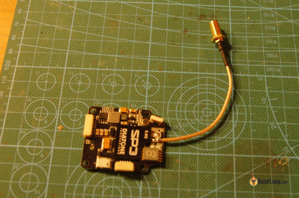
The Diatone SP3 VTX is a stackable video transmitter that can be mounted on top of the FC and PDB. In this review we’ll discuss the pros and cons after using it in a quadcopter.
This review is written by Grisha0 (intoFPV). The SP3 VTX was bought by Grisha0 and wasn’t sent to him for free (now you know this is going to be a fair review! :) )
Unboxing
VTX comes in a nice package that well protects the electronics. Board itself was vacuum packed in electrostatic protective bag. Beside the electronics you get 2 set of cables needed to connect power and telemetry (which is nice if you break it there is a spare cable). One nice accessory is USB extension cable which you can mount on your quad and have easy access to USB (I didn’t need to use it though).
Spec and Features
The Diatone SP3 VTX can be powered directly from LiPo battery up to 25V, and able to output filtered 5V power for the FPV camera.
It comes pre-flashed with MW OSD R1.6, what you need to do is to download the GUI, drivers and you are good to go with configuring your OSD.
The SP3 VTX is designed to be stacked on top of the FC/PDB, and it’s a potential space saver and makes quad builds cleaner.
- SMA Pigtail (antenna connector)
- Operating Voltage: 10V – 25V (input voltage)
- 5V 300mA voltage output (Filtered)
- PAL/NTSC compatible
- RF Output Power: 0.5mw, 25mw, 200mw, 600mw
- Weight with Pigtail: 12g
- Stack dimensions: 30.5mm x 30.5mm
- 48 Channels
- Board Dimension: 35.97 x 43.59 mm, height 5.47 mm
Setting Up
Mounting the VTX was very easy, connecting cables took only a few minutes. The hardest part was counting cables (in power plug) to find which one of them is 5V. Next step was to setup OSD, connection via USB.
Remember to look in the manual and check what drivers you need (I had to install 2 drivers), afterwards download MWOSD 1.6 GUI. One thing that I noticed was the fact that every option in the OSD was turned on, screen looked like a mess.
Initial Thoughts of the Diatone SP3 VTX
On the quad I am flying, I am using 3-lobe cloverleaf antennas and 4-lobe on the FPV goggles (Cyclops). I was using 200mW power, even though I was flying with a friend I didn’t notice any interference. Up until now I’ve used Eachine MT200 and Aomway 200mW – this is not comparable, stability and quality of the signal/image was much better with the SP3 VTX, even when flying behind trees etc. There is no additional filtering capacitor for the electrical noise and voltage spikes generated by ESC’s, yet the image is rock solid.
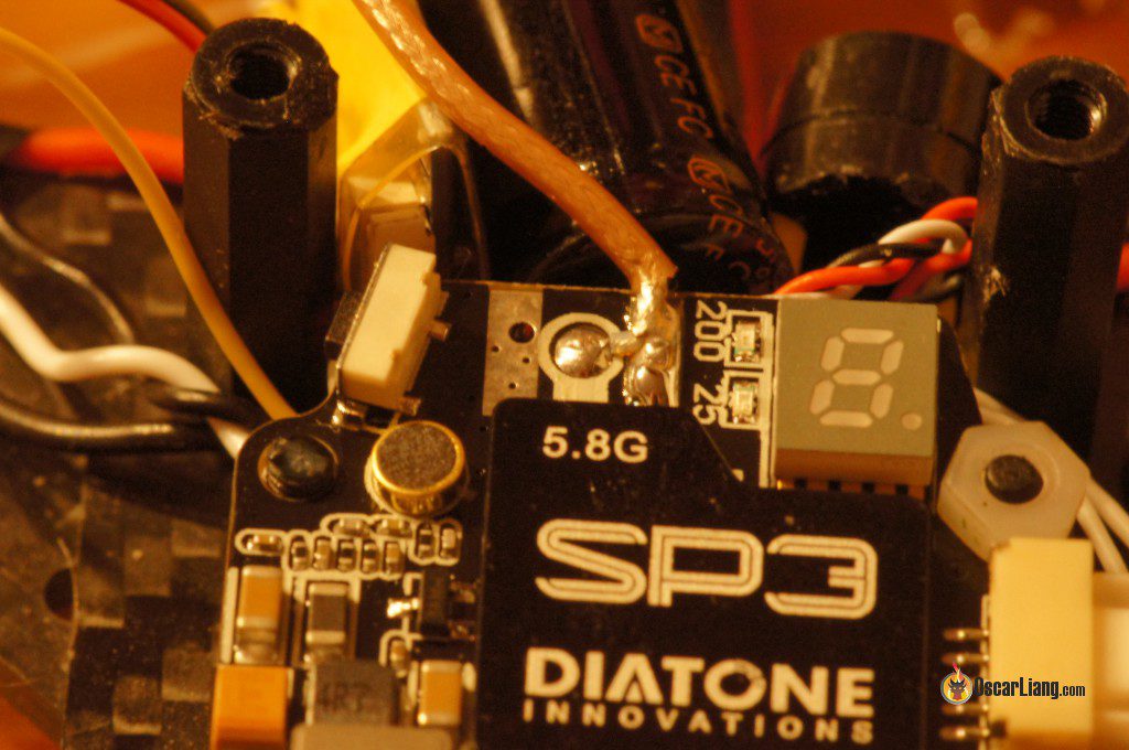
One improvement i would suggest to Diatone, is to reinforce the button. As users you can do that with a drop of hot glue. Another thing is the LED display which I think they could have tilted it a little. Because currently the LED display is mounted flat on board, after you have mounted the frame top plate and battery etc, you simply can’t see the readings.
Anyway, I will buy more of those VTX – yes they are not cheap, but the quality is good.
Wiring (In My Quad)
Here is how I connected the SP3 VTX to in my quad with FPV camera (Runcam Swift), Flight controller (XRacer), and Lipo Battery.
One funny thing is that one of the cables is not used at all – yet it is in the plug, so you get one extra silicon cable that is not needed for anything.
Here is another connection image with a D-link F3 AIO FC from Diatone.
Power and Range Testing So Far
- On 25mW, I got over 100 meters and image was still clear (open field, no obstructions)
- On 200mW, I got over 500 meters and image was still clear, no distortion what so ever (no obstructions)
- I was using 5.8GHz cloverleaf antennas on my quad and the receiver (no diversity)
- I haven’t yet tested the 600mW beside bench testing
Summary of Pros and Cons
Pros:
- Ease of mounting
- 5V Power stabilization for FPV camera
- External layer of connection cables is made of silicon
- Cables are good quality (no problems with soldering them)
- Cables are labelled (not necessary but nice touch)
- Cables have clip in (it will not fall off nor disconnect)
- Spare cables in set
- USB extension cable
- Pitstop mode (0 transmission as you change channels, you are not disturbing your flying friends)
- Nice packaging (plastic box – can be recycled for storing nuts and bolts )
- OSD already flashed with MWOSD firmware
Cons:
- Out of box OSD had EVERYTHING turned on (most of us only need voltage/timer)
- Heavy (if you are building ultra light quad, there are other lighter VTX options if you don’t need the OSD)
- Large size (due to stackability) – 35.97 x 43.59 mm (board dimensions) height 5.47 mm in the thickest place
- The button might be hard to reach one the quad is built in some frames (I am using the Nox5 frame, and the standoff is next to the button)
- Display is mounted flat on the board (when mounted in a stack you can’t see what is current setting, it would be better if it’s mounted sideways and reinforced with epoxy or hot glue) as you can see above on the picture
- Lack of support for the switch (I’ve added hot glue, others will add epoxy, if you will not do it as you push the button eventually it will break off)
Button Operation and LED Indication
- One button does it all
- Short Press: Switches Frequency
- Press & Hold for 2 Sec: Switches Frequency Band
- Press & Hold for 10 Sec: Switches Power
- 0.5mw, 25mw, 200mw, 600mW options
- Light off: 0.05mw
- Blue Light: 25mw
- Red Light: 200mw
- Red & Blue Light: 600mw
Author: Grisha0 (IntoFPV)


20 comments
I wonder if instead of using the software MWOSD R1.6 I could use the online editor found in the Chrome Web Store called “mwosd configurator”
How do I leave Callsign on?
The SP2 and SP3 both list audio input 0.5-2Vpp but wiring diagram does not show any input pins. Does anyone know which pins or pads are for audio input or is it a misprint? Thanks,
Is there a way to have it start in pit mode without selecting it at the end of the previous flight? Do I need to hold the button down for 20 seconds to get to 200mW from pit mode, or is it just 10 seconds plus a few more while it cycles through power modes?
Do you know if it’s possible to measure voltage through the “hardware pins”, rather than through the FC? Mine is coming up 0.0V for this, for both main voltage and video voltage. I’ve messed with the voltage adjust, turned on and off the reference voltage and nothing seems to change.
I’m having some issues with my vtx. I am unable to get it to connect to the GUI to do any set ups. It just say “waiting OSD” in the GUI when I try to connect. I see it is on comport 4 in the devices. I believe I have the right drivers installed for it, the Sil labs driver. I’ve tried just about everything I can think of. Do you have any suggestions. Is there a driver I am missing?
I get exactely the same , have you found a solution so far ?
How do I leave my name “Call Sign” fixed on the screen?
Another important issue
Do you connect your SP3 directly to the battery, so you’re not reducing the life of your product by letting it suffer so many voltage variations?
you can power the VTX from battery and it shouldn’t affect the life too much since it has filter. But it’s also a good idea to have LC filter on the power input for VTX.
Another question, using SP3 with the D-Link F3 v2 controller … On the Ports tab in my Betaflight, what should I leave enabled for the OSD to work?
Did you tell me that I need to enable MSP?
Is it possible to get this working with a kiss flight controller?
I’d like to know this as well. is MinimOSD and MWOSD too different for firmwares to be compatible? If they are. We should be able to flash this with the KISS OSD FW?
I did a little more research and it turns out MWOSD is a firmware for MinimOSD. So if a MinimOSD can be flashed with KISS OSD Firmware. Then my current educated guess is yes. KISS OSD should be able to be flashed to this SP3. I’m going to be ordering a KISS FC and an SP3. I’ll try to update here with results.
MWOSD is a MinimOSD firmware.
You can flash minimOSD with KISS OSD FW.
was anyone able to get the sp3 to work with their Kiss setup? I can’t find any instructions on how to flash the SP3? Thanks.
I am also trying to get the SP3 to work with my kiss fc, I have it working, it displays voltage and time but it has a message on screen flashing ” no data” “disarmed”. It won’t pick up data from the Kiss fc. The voltage displays because the voltage sense goes direct to the pdb main lipo connection. anyone with any updates on how to get the kiss talking to the SP3 would be big help.
Hy, how many mha it draws in max power?
Where can I purchase the cable set for OSD on the VTX to UART on the FC and the other wire set from the VTX to + and – on the FC and to the camera. Basically the the wires in the second pic in the “Wiring (In My Quad) section”
I like this VTX too, but on mine, channel selection is kinda messed up ..they go up sequentially: A/B/C/D/E/F, but thats not what i see on the display.
Also i find it a bummer that the 2-4s voltage input cannot be used to measure voltage. You have to use everything from the FC, except RSSI which the VTX can inject into the OSD.
Also i was unable to flash MW_OSD on it ..it says the schema is too big and won’t upload, which sucks cause i use dronin, and you need to recompile MW_OSD and activate settings specific to your FC to get everything working ..like PID adjustments.
I suppose they pre-loaded it with the CF/BF version. But i would love to be able to upload a reconfigured version…
Oscar, is it important to connect the ground cable on the OSD side ?