When choosing motors and propellers for mini quad, we often just listen to rumours, or what’s suggested by the manufactures. To determine the optimal motor and propellers combination for your quadcopter and multirotors, the most scientific way is to test it yourself. I tried to look for a ready-made motor thrust measuring stand, most of them are either too heavy (made of metal), too expensive, or out of stock. Looks like it’s time for some DIY fun.
Test video at the end of post. For more quadcopter tools check out our list.
Simple Motor Thrust Test Stand Design
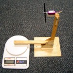
The trickiest part of this project was the design. Even with mini quad motors, such as 2206 or 2208 sizes can easily generate over 1KG of thrust on 4S. If the thrust stand is not well designed the result error can be large, and it can be dangerous if the stand is not stable with the fast spinning propellers. I went through quite a few usual thrust station designs, most of them has this common configuration. They all have relatively strong base to ensure stability (one of the reasons why many commercially available thrust stand are made of metal).
Basically, there are two wood pieces, the right angle arms, and the base. The two parts are connected by a hinge so the arms are movable. The motor is mounted on one arm, and as the motor drives forward, the other arm pushes against the scale to indicate thrust generated by the motor and propeller. It’s simple enough to build, but requires tools and material that I don’t have on hand (drill, wood pieces etc). So I did my usual thing, sketched random stuff on paper and finally I settled on two even more simple designs.
The first design is quite similar to the above example, only it would be using only one straight wood piece, and it works like a balance or seesaw. The disadvantage compared to previous design is that the motor/prop is too close to the ground, which affects aerodynamic and the thrust generated.
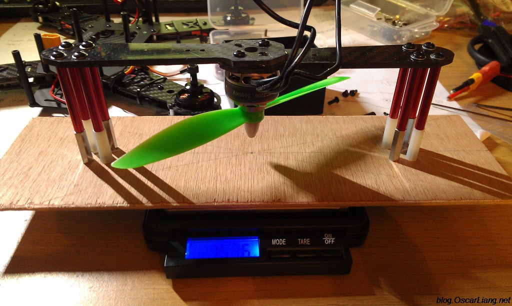
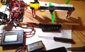
Second design is my favourite, it involves no moving parts (no pivots), and I am able to utilize material that is available to me, some ZMR250 spare arms, and some spacers. The thrust will be pointing downward, so in theory this thrust stand should be relatively stable, I just need to make sure there is enough friction between the bottom board and the scale. Drawbacks are again, it’s too close to some surface and affects accuracy (thrust generated), also the props size that can be tested is limited by the size of the arms (how far the spacers are from centre). But I am mainly going to test 5 inch and 6 inch propellers only, so that’s not a problem.
Of course you also need a watt meter for recording current / voltage as well, and a servo tester to control the ESC/motor speed.
Building DIY Thrust Stand
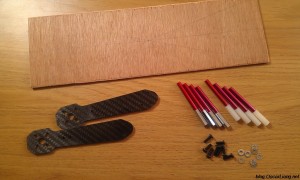
So once the design is done, the rest is easy and straight forward. Here are the material and parts used.
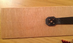
Find the centre of the base plywood board, and find out where we need to drills holes.
I used a sharp knife and a pair of scissors for the job.
I glued the two arms together with Epoxy Glue. Once you fasten the motor on the arms, it also holds the two arms together firmly, so in theory you don’t even need to glue the arms together, but it’s more convenient to do so.
And I am happy with the result :D Added some foam at the bottom to make it a bit less slippery.
And finally tested it with a motor with watt meter, worked perfectly.
Here is a quick video showing the test:
Just another example :)
https://www.youtube.com/watch?v=LDu3Aww-koU
Accuracy?
Many are doubtful about how accurate this DIY gadget is. Some pointed out there is air flow issue as the propeller is so close to the bottom board. Indeed this is a issue that can affect final reading, and I did observe some inconsistency when measuring larger props on power setup.
I concluded that this thrust stand is good for measuring thrust range up to 500/600 grams. Anything larger than that, reading will be reduced than actual figure. I had pretty accurate reading with 1806/2204 motors with 5inch props, compared to manufacturer’s data.





12 comments
Hi, I want to recreate this for my highschool physics experiment, wherein I measure the thrust generated by different pitched propellers, I was wondering how I can interpret the data produced in grams and convert it to Force, since force is M*a and thrust is a force.
https://physics.stackexchange.com/questions/702730/convert-bldc-motor-thrust-in-grams-rm-g-to-newton-rm-n
The Simple Motor Thrust Test Stand Design worked for me just fine. Thanks for showing me that design!
I’m thinking of doing something like this, only I want to flip my whole 3″ quad upside down and secure it to the scale directly. As far as airflow considerations, would the effect be linear across different motors and props, given the same placement for each test? In other words, would the results allow one to at least effectively compare which combination gives the “best” thrust, if not give an accurate thrust reading?
Has anybody got any links to other test stands? Preferably one I could use to test the control algorithm for the motor too.
What if you need to measure larger props that your side mounts???
this stand is designed for 6″ props or smaller.
Hello, for the sake of cheap and wonderful diy i made this: hackster.io/vincenzo-g/diy-thrust-station-f69b60 maybe you will find it interesting!
Doubting about air flow ? Why ? The proppeller suck the air from under and push it to the top … and I think that the arms shape is what you will find when building the quad , motors never flys alone , they are allways screwed on an arm and the arm make some air flow fluctuations . I think it’s the best way to have the best result against another system. The “L” type is less accurate IMHO because you have to build the system with strict measurement between motor axis , and the “L” axis , and from the “L” axis to the touching point on the scale to have the same “strength momentum” according the axis at the bottom of the “L” … not easy as it seems :)
My quick and simple I’ve was like your see-saw sketch. I clamped it to a table with prop hanging over to have a clean unrestricted air flow.
Good work as usual.
Suggestion:
Mount the motor on top of and mount and inverte the propellers, this way You can test propellers larger than 6 ”
I’ve seen several videos of motores test made this way.
yes good point :)
the reasons i have the motor below to the arm is safety, and the stand is more stable. also it’s easier to mount the motor on it as the screws are point up :)