
Great robots deserve a great remote controller. A proper, well designed controller can speed up project development and in some cases can even improve robot performance. In this post I will describe how I design, make, test and improve a customized RC remote controller.

I call this project “Omote” – Oscar’s Remote controller. (Just to clarify, it has nothing to do with the Japanese word Omote which in Aikido, it could mean the act of throwing your opponent in front of them, thanks to John Matsson pointed that out, haha
The Omote Goal!
The goal of this project is to create a remote controller that can be alternative to a RC transmitter or similar commercial controllers. The remote controller we build would be able to control, manipulate our robots, flying planes like quadcopter, even can be used for PC gaming like car racing games. There are quite a lot of existing commercial controllers like RC transmitters, but they tend to be very expensive and probably not optimized to the project we are doing.
We are going to focus on
- affordable
- customization
- multi-purpose
- latency
- accuracy
- reliability
- operation distance
- informative
This is the final product. It’s not perfect, and I learned a lot from this trial version. So I might think about making an new version when I have time.

I will divide this project into these tasks. And hopefully at the end we will have a reliable working remote controller.
- Hardware and Software
- Communication Protocol Design
- Calibration
- Max Performance Testing
This is the LED and Servo Control Demo video:
Remote Controller Hardware And Electronics
I tried to use parts that are as simple and cheap as possible. But what components to pick largely depend on what kind of project or robot you are trying to control. For example for a simple robotic tank, you might want to be able to make it go forward and backward, turn left and right. So four push buttons would be enough to accomplish this. But if you want to have better user experience, a joystick would be better. If there is a canon on the tank, you probably also want a button for shooting. If there is a head light, you will need a toggle switch. You should see where this is going.

For my remote controller, I am not designing it narrowly for some particular projects, but for more general usage. Therefore I used a combination of different types of control components. This is what it looks like on drawing.
Here are the parts I used:
- Toggle Switch x 4
- 2-Axis Joystick x 2
- Potentio Meter x 4
- Push Button x 6
- LED x 3
- LCD x 1
- Arduino Mega x 1
- Cables x many
- Small Breadboard x 2
- Ciesco XRF Wireless Modules x 2
For the Wireless communication Modules, I chose to use the Ciesco XRF because they are so much cheaper than the XBee. I wrote a post on how to use them, check it out it’s very straight-forward. Xbee would also work.
I picked the Arduino Mega because I know Arduino very well. The Mega provides more enough Analogue and Digital pins, which the UNO failed.
I was thinking of getting a 3 Axis Joystick, but they are shockingly expensive! The cheapest one I found was 30 Euros which is literally just a 2 axis joystick with a potentiometer. So I went for the cheap option of getting these two parts separately and it costs me only 3 pounds.
Table of Contents
Inputs of These Components
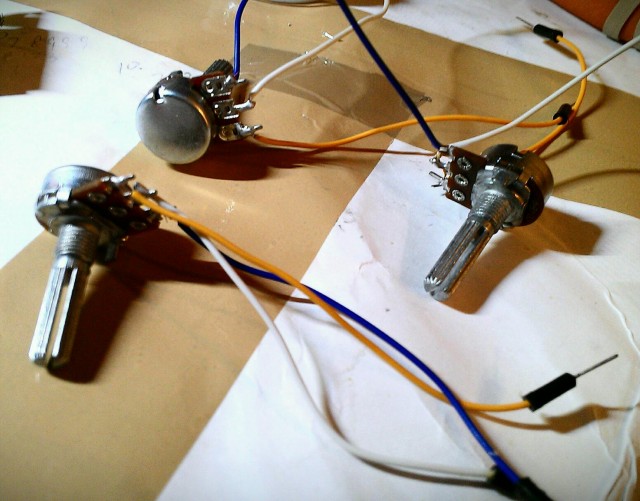
Toggle Switch, Push Buttons return true when pressed (1) and false when it’s not (0). Potentiometer has a max resistance of 10K which give a value between 0 to 1023. 2-axis joysticks are basically just two potentiometers, which gives you two values between 0 to 1023 for X and Y axis. It might be a good idea to test and make sure you understand how these components work before doing any further. The picture shows the testing setup I had.

Soldering and Assembling
Assembling wasn’t particularly difficult as everything went quite smoothly as planned, though I had to turn some parts around to fit the actual dimension. Here are some soldering work I did on the parts:


Male to Female cable made by myself, they are very handy to have.


The Arduino Mega is attached to the base board. And the white front panel finished using Polystyrene.


This is what happened when I put every components on the panel, it’s a mess! But when I turned it over, I felt much better, LOL.


It took me about 2 to 3 hours to finish the final hardware testing after the assembling. And that’s it! All the parts are working and ready for programming!


Some Assembling Advice
Make sure you have all sorts of jumper cables ready: Female to male, male to male and female to female. And make sure they are long enough, generally you want them to be twice as long as the width of your remote controller, so you can have the panel and base laid down naturally side by side while you are connecting the components. Otherwise you will have a really painful time doing that. For trouble shooting, it’s even worse when short cables are used.
Carry out testing right after you connect a component. It would be a nightmare to have all the parts connected and realize nothing works!
Software Overview
Software for this project consists two parts, one for the remote controller (which I call “Host” later on), and the other for the robot (“Client”).
The source code can be found here: https://code.google.com/p/diy-rc-remote-controlle/source/browse/
As for software for the remote controller, the idea is quite simple (see state flow chart). But I can foresee to achieve what is required, the programming can get very sticky and complicated. It is responsible for initializing connection, re-establishing broken connection, encoding commands and provide feedback from client to the user. There will also be a LCD menu system to provide current state information of the controller, allow real time parameter adjustment, calibration and so on.
You might notice there is no setup and loop functions in the client header file, that’s because it’s just a header file that contains some useful functions, which you can utilize in your client sketch. You will need to write your own client sketch (which contains the setup and loop functions), since everyone will have a different purpose what the client side does.
Your can follow this example on how to use the client side functions.
// This example reads input from a potentiometer, to control the LED brightness.
#include "control_omote.h"
byte LEDBrightness = 255;
byte ledPin = 5;


void setup(){

	Serial.begin(9600);
	delay(500);

	// establish connection
	Serial.write(1);

	// define pin for LED, and power it on
	pinMode(ledPins[0], OUTPUT);
	digitalWrite(ledPin, HIGH);

}

void loop(){

	if(ReceivePacket()){

		// =================== Do stuff here =======================

		LEDBrightness = map(pot4, 0, 1023, 0, 255);
		analogWrite(ledPin, LEDBrightness);

		// ================ end of do stuff ==========================

		SendFeedback(1);
		delay(50);

	}

}

On the client side (robot side), I will be writing a library for it which will act as an interface between the robot and the controller. It is responsible for accepting connection, decoding commands and communicating back.

Arduino Function For Fundemental Communication
As for sending data, because we are using the serial pins on the Arduino, I will be using Serial.write() for sending data. This function sends one byte of data which means the max value we can transmit is 255 each time we call this function.
You might be wondering what we should do about the inputs from the potentiometers and joysticks, as they have a max value of 1023. We have two options, one is to downgrade resolution to map the value between 0 and 1023 to a new value between 0 and 255, which can be fit in one byte. Second option is to treat the number in term of bits (1024 can be represented with 10 bits), which can be send separately as two packets. When they arrived at the client side, we put them back together as one number.
As you might know, for a single value, sending two bytes would take longer than one byte. Although it’s less accurate, we sometimes don’t need that level of accuracy and prefer smaller latency. So I am planning to adopt both methods into the remote controller communication, so user can select which way to go depends on the situation.
Controlling a robot with this controller!
And that takes us into the next section – the protocol. How do we design and put together a command from these raw input values for transmission? It’s going to be a wordy topic, so I will talk about this in the next post.
69 comments
Great Job!! I need a remote control transmitter and receiver for a project that I’m building. How do I get started??
Please help me by giving details of the drone transmitter circuit diagram.
And the connection of the receiver to the motors with circuit diagram of the receiver.
Every thing is fine.please tell us the how to connect all the components in the transmitter? post the circuit diagram.
Sir can I use GPRS sheld instead of wireless module to control drone by GPRS
Can you tell me the code if i wanted to use a normal rf chip instead of the ciesco xrf chip.
THANKS.
Hello good day, I really like what you did please could you help me with a detailed explanation of how you connected the hardware, a circuit diagram would be most welcomed.
can I use this for an RC car? if so, is it compatible with a rx2c controller? I have an old RC car that the controller got left in the rain by my son, and I need help with building a new one.
how do I connect this diy controller to my quadcompter
I’m interested in your code, but as Google Code is down, it is not available anymore. Can you provide us with your code somewhere else?
hey oscar ,
Can i use this remote for a quadcopter??
Hi,
I am new to arduino and especially wireless communication. I have a couple of NRF24L01 and I was wondering if I could use those instead of the XRF wireless module? If so, what would I have to change in the code?
Thanks
what components would you put in the robot to talk to the controller. ie Raspberry pi? another arduino?
Hi Oscar, I went to the forum below, intofpv.com since I had some questions about robotics, but did not see any thing there. Is that the right forum? Thanks
nah…. the forum is for multicopters only… you can still ask questions in the comment though regarding robotics…
I tried the link but there is nothing to download.
Hi Oscar
I would like to make this type of RC Transmitter with your firmware.
But I have a problem…
I am going to use this for a micro quadcopter. But, what could I use for the throttle? The 2 axis joystick would not remain at the same position. And If I remove the spring in it, it would be successful, but it would move sidewards. (the direction for throttle is up / down, but it moves left/right also).
I feel not to use 2 axis joystick for throttle. If you have an idea what to do, please reply… And also if you know about potentiometer which is up/down (without spring) only, please inform me…
Thanks.
a slider maybe? or get a RC gimbal that has a throttle stick.
Hi Oscar
I am following your blog regularly and got great information.
rcbazaar.com
Hi Oscar
I would like to know whether it could be used for under water remote controll wireless communication.
how many channels are on this one ?
it’s user defined :)
Hi,
I’m really interested in this project do you have a wiring diagram For hand held control?
And could you do a more detailed client script to connect to a multiwii quadcopter please
Hi,
I had a go today see if I could sus it myself.
my host xbbo has a solid red light.
and my client is flashing believe they our connected
I have the above script flashed to my client arduino nano with the control_omote.h
My question is is the control_ protocol.h just a header file for host side or is it a .ino that’s flashed to the mega as this is what I have tried and I have a pot in A1 host side and a led in pin 5 clinent side but can not control the brightness.
no i don’t have wiring diagram… for connection check the Arduino sketch.
I haven’t tried it yet on a quadcopter.
hi,
Thats ok ive started to work bits out on my own.
can yo tell me where im going wrong on my client sketch i want a second pot to control another led do i have to can anything in thr control omote lib?
#include “control_omote.h”
byte LEDBrightness = 255;
byte ledPin = 5;
byte LEDBrightness2 = 255;
byte ledPin2 = 6;
void setup(){
Serial.begin(9600);
delay(500);
// establish connection
Serial.write(1);
// define pin for LED, and power it on
pinMode(ledPin, OUTPUT);
digitalWrite(ledPin, HIGH);
pinMode(ledPin2, OUTPUT);
digitalWrite(ledPin, HIGH);
}
void loop(){
if(OM_ReceivePacket()){
// =================== Do stuff here =======================
LEDBrightness = map(pot4, 0, 1023, 0, 255);
analogWrite(ledPin, LEDBrightness);
LEDBrightness2 = map(pot3, 0, 1023, 0, 255);
analogWrite(ledPin2, LEDBrightness);
// ================ end of do stuff ==========================
OM_SendFeedback(1);
delay(50);
}
}
How do I add a second led to be controlled off a second pot?
Currently I have 2 pots setup but only one controls brightness of the 2 LEDs how do I define which pot is to go to which led, sorry this is a big learning curve for me
Hi Oscar
Ricky in your sketch you are only referencing the LEDBrightness variable and not the LEDBrightness2 variable
I have made the offending variable bold below.
LEDBrightness = map(pot4, 0, 1023, 0, 255);
analogWrite(ledPin, LEDBrightness);
LEDBrightness2 = map(pot3, 0, 1023, 0, 255);
analogWrite(ledPin2, LEDBrightness);
If you could post or send schematics of this project will be great.
Is there any reason you can’t post or send the schematics?
Hi, I am interested in this Idea. me and A friend are going to build a quadcopter and I think the is would work, I’d love your cooperation if you could help us out!!! aso, can I use Arduino Uno instead?
Hi Oscar,
can I use Arduino Uno instead?
Thank you
Andrea
yes, but it doesn’t have enough ports for all the controls..
I could not find the schematics of your Tx
Hello Oscar,
I would like to ask you if you could send me materials for build your remote controller,please. Excuse my bad English, please.
Thank you very much
Hi Peter, Sorry what do you mean by ‘materials’? All my pictures, schematics and codes are on the page…
thanks
Oscar
I thought the host source code for the Arduino, because when I download the file specified does not contain a file with the extension .ini file, but the file with extension .h, which does not prepare me Arduino.
That’s right, the .h file is the header file (same as C++). There is no ini file.
Again the place to download is
https://code.google.com/p/diy-rc-remote-controlle/source/browse/
How do I upload to Arduino mega? When I tried it error occured: “core.a (main.cpp.o): In function` main ‘:
C: Program Files (x86) Arduino hardware arduino cores arduino / main.cpp: 5: undefined reference to `setup ‘
C: Program Files (x86) Arduino hardware arduino cores arduino / main.cpp: 15: undefined reference to `loop ”
oh I see what you mean.
No you cannot compile them directly, the files I provided are just library files, which gives you an idea how I program my remote controller.
You will need to write your own code, depends on what controls you have.
I will have a look if I can find my full source code for the Arduino, and I will upload it.
Can plz make a remote control without using arduino. It’s for my project rc car or plane…totally lost since I have to make every component.would be very cool if u can help me understand radio controlling using analogue mostly.tyvm
You can do it…
Just use a ATMEGA 328P – PU microcontroller to standalone without using the commercial arduino ‘BOARD’.
But the controls will be a limited because it has a limited no. of pins than ATMEGA 2560 ic. Just google for ‘arduino barebones’ or similar (homemade arduino)…
Thanks! I’ll try to figure out the rest on my own. You were a huge help ;)
-R
Sorry, can’t help, I’m a middle schooler, no credit card… But I figured out everything but the robot side hardware… What do you think I should use? Also, the dalek model (if you want it) can be found by googleing tv/countdown paper dalek. I glued the designs on a cereal box before cutting them out, which also makes the body cheap. Sorry for the horribly long comments, this is kind of how I write online. I just need to know what to use on the robot side of things to communicate with the remote. Thanks,
-R
The designs were also enlarged by to fit about a whole sheet of paper. To enlarge, click on the image while on Google images, which shows you that big preview, then right click, press open image in a new tab, then right click THAT, theme you’ve got a good dalek :)
the Xbee or XRT module seems to be fine for this purpose. Even simple bluetooth transceiver should just work fine, but the range might be shorter.
The board & stuff gotta fit those dimensions. It’ll be quite the challenge :D
I’m using an arduino uno, one toggle switch, that rc receiver thing you mentioned/used, and two joysticks (and, obviously, wires). I’m not sure what to do next
Might use one joystick, as it’ll be a really simple first project (I hope ;) ) BTW, sorry about the large sum of comments. This is my first robotics project, and besides by robotics teacher (my middle school rocks!) I’m not sure who to ask…
yea, build one first with just one joystick and some simple control components, You will have many ideas, and improvements after this, and will want to build a second one! :D
I haven’t got any components at the moment, all my money went into Flying machines.. haha… if someone would like to sponsor me I would do it :D
Or at least a 2 wheel robot? Please? Mabye? It’s also 1×1.5 inches. I challenge you to try :)
Can be 1.5-2 inches tall.
Could you post a tutorial of how to make a tiny dalek? I am using your project as a guideline. PS don’t bother trying to respond to the provided email. It won’t work :/
hi,
i cant get the client side of the code to compile and run im new to arduino and this is most likely the issue can you help me please.
it’s not compiling because you need to write a sketch for it. see my above comment.
Hi,
Sorry for the double post was doing it from my phone and didnt think it went through.
could you help me more I have just stared with Arudino’s and looking at scripting the clients side to act as a reciever to interface with multiwii. so forwards back rotate. altitude hold switch ect. with the client scrit you upload i get this,
RcReciever.ino: In function ‘void setup()’:
RcReciever:17: error: ‘ledPin’ was not declared in this scope
RcReciever.ino: In function ‘void loop()’:
RcReciever:24: error: ‘ReceivePacket’ was not declared in this scope
RcReciever:29: error: ‘ledPin’ was not declared in this scope
RcReciever:33: error: ‘SendFeedback’ was not declared in this scope
Probably a easy fix but im a noob wanting to learn please help.
Hi,
I am trying to use your source code for my project and host side is fine but I don’t understand the client side as it don’t have a void setup or void loop so will not compile, also instead of using crf or xbee can I use 3dr wireless modules?
Thanks for Any help you can provide
Hi, what I provided is just a header file that contains some useful functions, which you can utilize in your client sketch.
You will need to write your own client sketch (which contains the setup and loop functions), since everyone will have a different purpose what the client side does.
I admit I missed out some guide lines on this, I will provide an example how to use the these functions. Check this post again under the download link.
thanks
Oscar
Hi,
Your project is pretty awesome, Oscar. I am also currently trying to make a remote control but I am stuck on the coding side. Would you be able to send the code for the transmitter and receiver.
Thank You,
Kyle Y
I am sharing the source code, check “Software Overview” section.
Hi Oscar!
Nice work!
Can you share the Arduino Mega Transmitter code? Any information about the receiver (client side)?
I´m assembling a tricopter and i don´t have the controller. I think that i can use this project for this. I have same Xbee modules to make this too.
Thank´s & Best Regards,
Dilso
Oscar, this is a beautiful project. I’m building a vtol hybrid uav. I believe this controller will work for me. If possible, could you pm me a list of everything I need to run this and ur code and possibly hints on this setup. Thank u. I would also like to donate $ for this, I figure u will save me, so I will pass it to u. Thank u again for being a great mind.
Hello,
You can find the components required to build this controller. However to control a UAV (whether it’s a car or airplane) it would be better to replace the game console style joysticks with proper RC transmitter joysticks for much better controllability.
No problem I will send you the code shortly, it’s not very good documented, but do ask on the forum if you have any questions.
Hope your project goes well :-)
Regards
Oscar
Thank you. Just leave me info on how to donate when u send me the p.m. yes, its a nice fun big project. Tri-90mm edf vectored thrust in vtol mode, in high speed mode the outboard edfs rotate with their corresponding thrust vectoring units. debating on using any flight surface controls, or just staying all thrust vectored and using middle edf for stability or advanced maneuvers. I figure 12 channels is a good start and maybe adding another xbee for the video and other comms. Lol, seems to get more advanced as I go, funny how that works. Yes I was wondering on the joystick style, but I may just use a pointometer for throttle and multiposition switch for the out board edfs tilt. Thank you again.
please Oscar i will need the connection shematics of the DIY Wireless RC Remote Controller for Robots, Quadcopter. tanks
Following up: I now have most of the parts I need, but I still need to order the RF transmitters – I think I’m going to spring for the XBee modules. Tomorrow I’m going to Radio Shack to pick up an Arduino Mega (I only have an UNO and need the extra pins.)
UPS just showed up, and my 2nd joystick breakout is in the box. This will be fun!
Yes! :-)
one of the most exciting moment doing a project, is the moment you receive your parcel… LOL
Absolutely! I had to wait 3 weeks for my L293D ICs that I am using for H-bridge motor drivers on a small RC car project – I was so thrilled when they finally arrived!!!
I’ll be sure to share photos of my controller – I will be using this site as a reference during the build. I may use a slightly different layout, but I will be including the LCD screen (with backlight) and maybe only use 4 potentiometers. I am using x2 SainSmart joystick breakouts I found on Amazon and will use the 6 button and 4 toggle switch setup you have shown here.
Great post, Oscar! I plan to make my own and will be using this awesome post for a reference – I have most of the parts already, but need the RF modules. I thought about using XBee modules instead, but it looks like the Ciseco XRF is going to be MUCH better bang for the buck — I just have to ship to the U.S. and can’t take advantage of my free 2-day shipping on Amazon.
Thanks again — I’ll be sure to share my experience with you!
Omote is also a japanese word, perhaps you know that already. Itś used in Aikido e. g. Every throw and pin etc can be done in front = omote, and behind = ura of the opponent. Its a perfect name for your controller since itś so beautiful frontside among other translations.
Hi John
LOL
I didn’t know that word in japanese! it’s good to know ‘Omote’ has got more meanings than just a robot controller! :-)
you must be a kick-ass martial art master to know that, (laugh)
cheers
Oscar