PWM and PPM are two of the radio receiver protocols used to transfer data from RX to the flight controllers. In this article we will explain the differences between them and how to convert one to the other.

PWM and PPM Introduction
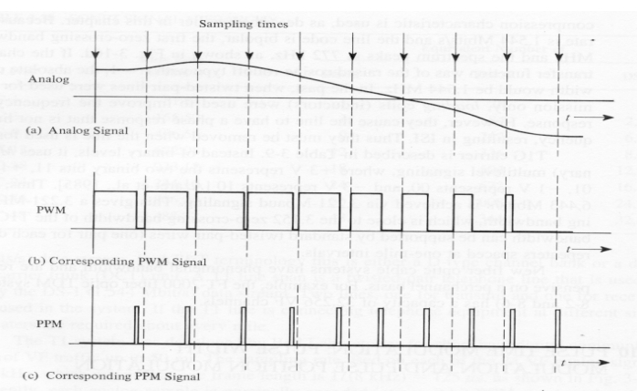
PWM stands for Pulse Width Modulation and PPM stands for Pulse Position Modulation. PWM is a technique used to relay data in the form of a varying pulse width. In PPM (Pulse Position Modulation) the analogue sample values determine the position of a narrow pulse relative to the clocking time.
RC Devices that use PWM Pulses:
- Servos
- Electronic Speed Controllers
- R/C receivers
- Data loggers
- Autopilot/Stabilization systems
- Servo Controller
RC Devices that use PPM Pulses:
- R/C transmitters
- R/C receivers
- Autopilot/Stabilization systems
- PCTx
PWM – Pulse Width Modulation
In PWM each RC channel has it’s own cable. If we want 9 channels we must wrie all 9 cables along with the power and ground. The value of each channel is represented as a 1 millisecond (ms) to 2ms “ON” signal and this signal repeats (or updates) every 20 milliseconds. It goes high for the 1-2ms, then it falls to Low. The length of time it is high is the value for that channel. We see this in the GUI directly as 1000-2000, so we are seeing the raw ON time in microseconds.
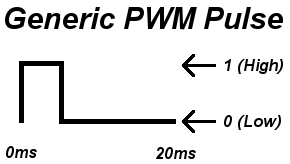
The whole frame is 20ms long, the important part of the pulse is the time the pulse is on; 1-2ms. Although the time between pulses is not as important it does play an important role. Usually keeping the time between pulses around 20ms is best. If the delay is longer, a servo for example will lose holding power. A pulse can be generated much faster but 20ms is best for most situations.
PPM – Pulse Position Modulation
Think of PPM as several PWM signals lined up back to back (not really, but that’s what it does). In PPM, the same signalling is used but each channel is sent successively, then a delay, then it loops back to channel 1.
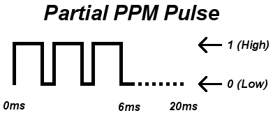
In normal PWM there are 50 updates sent per second (50Hz) which means each update takes 20 milliseconds. So if each channel takes up to 2ms, then we can do 10 channels within that 20ms before which we need to loop back to ch1. So we don’t even have a downside of multiplexing all the channels down to 1 wire and yet we have less wiring, and in our case 2 extra AUX channels! If you can do PPM, it’s better!
However PPM is not the most popular because many radios don’t support PPM. If you don’t have a PPM transmitter and receiver you can use a little device that converts between regular PWM and PPM. The MultiWii supports PPM input. Just define the appropriate option SERIAL_SUM_PPM in config.h and wire the PPM signal into the Throttle channel. The rest of the transmitter inputs like roll, pitch, and yaw are now free for other things. It is also possible to obtain PPM from PWM by using a mono-stable multivibrator circuit.
Conversion example
Here is a DIY project that uses Arduino to convert PWM into PPM signal.
You can buy PWM-PPM converters: Amazon | Banggood | GetFPV
15 comments
Hi Oscar,
Stunning resource.
Does anyone know the PPM frame rate Futaba uses for the trainer system?
FrSky seems to use 20.0ms 300u (what is the 300u part?)
PPM encodes and concatenates individual channel’s pulse length to a pattern that a allows a decoder to easily measure the time from rising edge of this channel to the rising edge of the next channel (this is for non-inverted PPM, for inverted it’s falling edge detection). Here’s some pseudo code for PPM encoding:
max-channel-number = 8
next-frame:
wait 4 milliseconds (frame gap = signal end of frame)
channel-number = 0
next-channel:
pull the pin high (first rising edge)
wait 300 microseconds (here’s your 300u)
pull the pin low
if channel-number equals max-channel-number then goto next-frame
pwm = channel-numbers pulse length (example 1600 microseconds)
wait for pwm-300 = 1300 microseconds
increment channel-number (at this point 300+1300 = 1600 microseconds have elapsed)
goto next-channel
I’m a bit confused.
If we add 1.5 ms at te Start, then 2 (max) ms for each channel, if we have 4 channels, how do we reach 21.5 ms for a complete 20ms frame? Do I have to vary the duration of the LOW level between pulses to reach 21.5 ms?
PWM is a Pulse with a width of between 1and 2 mS. Each channel of a transmitter has its own pulse within a series of pulses all sent as a frame in a total of a 20mS time frame. We all know the A,E,T and R channels followed by convention, with Gear being ch 5 and Flaps Channel 6, yes I know, this is for a conventional type aircraft! So maximum times for each channel is 2mS. It is theoretically possible to have 10 PWM channels, unfortunately the “frame” needs a start and a finish which the receiver can recognise. The Start is a relatively long space of more than 1mS, typically 1.5mS. The end of the frame is easy, 20mS from the first data pulse start. So although a “Frame” is 20mS, it is always preceded by a 1.5mS space, so total “Frame” duration is 21.5 mS minimum. Positive going pulses are called “Marks” so the converse are known as Spaces. Each Mark has a leading edge, following our convention one occurs every 2 mS, followed 1 to 2 mS later by a trailing edge. To convert PWM to PPM you produce a short Mark at the TE of the PWM Mark, so instead of measuring the length(width) of the pulse, we measure the time between the start of the frame and the leading edge of the Pulse. This can be at full (for the sake of this example) left Aileron a value of 1mS. 2mS is allowed in total for that pulse, so the Elevator at max down occurs at 3 mS, or fully up, at 4mS. Similarly for Throttle, start at 5mS and end at 6mS, etc. Until we reach 20mS. The PPM pulses are very short. Does that make more sense?
Actually, it IS correct that PPM is a series of PWM lined up back to back, they are just inverted too. Actually, that is how transmitters modulated the RF back in the day: They digitized each channel into the length of a space each, one at a time, with a short pulse in between. To signal the start of the pulse train, a longer pulse preceded the first space. This was also the very signal sent between transmitters when you used a trainer cable. In the receiver end, the same signal was available right after the super heterodyne receiver, before it was fed into the last chip, which inverted the signal and output each of the pulses on a different pin. For the electronics buffs, the last chip was a decade counter, being reset by an RC filter tuned to the length of the leading pulse.
“In normal PWM there are 50 updates sent per second (50Hz) which means each update takes 20 milliseconds. So if each channel takes up to 2ms, then we can do 10 channels within that 20ms before which we need to loop back to ch1.”
I find this wording slightly confusing… I understand it like this: “In normal PWM there are 50 updates sent per second (50Hz) which means each update takes 20 milliseconds. With PPM, each an update for a channel takes 2 ms, so we can do 10 channels in that 20ms period, before looping back to channel 1.
Additionally you say “channel is sent successively, then a delay,”… so how does that delay fit in this 20ms period? There must be some time reserved, so you wouldn’t be able anymore to update 10 channels of 2 ms ?
It updates ever 2 ms 10times to make 20ms intervals and it can do that 50 times per second.
You cannot do 10 ch in PPM , you need some time for the Sync
PPM and PWM are used to send analog signals, not digital signals. They are analog protocols.
Thanks for this, its just what I wanted to know, and for your analogy of PPM being like a train of PWM is not confusing at all. I know its not an exact analogy but it does allow someone who understands PWM to visualise the difference.
Hi Oscar,
Sorry, but your comment that “PPM basically is several PWM signals lined up back to back” is technically incorrect. PPM and PWM are two different ways of encoding information into a data stream. I am not sure why you keep repeating this error. You seem to understand what PPM and PWM are. One varies the width of the pulse (PWM), and one varies the timing. One is not a series of the other.
Actually, ‘pulses’ are simply another way of expressing timing. The “back-to-back” comment is correct: the lengths of the PPM pulses are proportional to what they would be in PWM, expressed in a different frequency domain.
Right after he said that he said not really go back and read it again before you start bashing somebody man
Hi Oscar
Thanks for this write up. Trying to figure out all this stuff as I’m tinkering with R/C and Arduino/IOIO applications.
This is great information, But i would be complete if you have added how can we convert PPM to PWM and vica versa.