The Radiance FC is a new line of stand-alone flight controller by FuriousFPV, a company that is known for the insane amount of innovation they have been coming up with the last few months.
FuriousFPV have created 2 flight controllers that have PDB integrated, the Piko BLX and Kombini. So far from the info I have gathered, the Radiance is basically a Kombini without PDB. It’s aiming at users who wish to run a separate PDB, and only want to get a stand-alone flight controller more cheaply.
Retain price of the Radiance FC will be $29.95, and they are aiming for October 2016 release.
This FC is still being developed and there isn’t much info available yet. What we are looking at here is just a prototype board I received, so there are likely some changes to the Radiance FC in the final version.
Specs and Features
- F3 Processor
- MPU6000 ACC/Gyro Sensor connected with SPI
- Supports 2S-6S LiPo battery Input
- Onboard 5V (2A) /12V voltage regulators with LC Filter
- RX: SBUS, PPM, Spektrum Sat
- 6 ESC output – Supports Hexacopter
- ILAP transponder
- RSSI and Current Sensor Input (still requires an sensor)
- Size: 36mm x 36mm
Although being a stand-alone FC without PDB capability, it has basic 5V BEC as well as 12V voltage regulator (with LC filter). That allows you to power the FC directly from battery, and it cleans up the wiring as you won’t need to connect additional VBAT cables. The 12V output can be used to power your FPV gear, a pretty neat solution.
It has a bootloader button for easy firmware flash. The board is similar shape to the Lumenier LUX F3, and I really like the ESC/motor signal layout.
By the way it uses the same firmware target as the Kombini and Piko (not in official repository yet but hopefully it will be soon).
- Raceflight: https://github.com/NightHawk32/raceflight/releases
- Betaflight: https://github.com/NightHawk32/cleanflight/releases
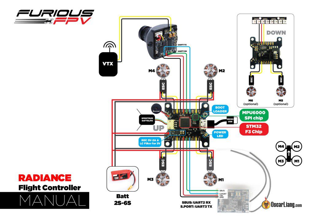
Pin Layout and Wiring Diagram
Like I said, this is just a prototype board, and there might be some changes to the board. This is only a sneak peek post. One example would be 12V. There is no 12V output on the prototype but it should be added in the final product. Same reason for the IR transponder, not available yet on the prototype board.


11 comments
Hi the solder pad for Sbus came off. Is there a way to use another UART and use it for Sbus.
Apologies if unclear as I am a newbie on quad building
yes just pick another UART (RX), and configure in the software for serial receiver, SBUS.
Does the radiance fc have telemetry pads like the lumenier lux v2 it got its own telemetry pin hole,pls help tnx
I would like to thank you for this info,anyway little problem I’m using frsky x4r-sb receiver sbus and using the new Radiance fc but I got a questionsink (1) how to sbus wiring this fc and (2)where’s the telemetry pads,on your sample pdf you’re using frsky xsr as a receiver but not frsky x4r-sb. Can you pls help me and others have or similar questions. Thanks
Why do you need a PDB if you the FC already have 5v and 12v regulators?
it’s for connecting the battery with the ESC. And because it also has pads for VTX/Camera/OSD it makes wiring cleaner
What??pls explain tnx
Where is the 12V rail on the board?
the board i got is a prototype and it hasn’t got 12V yet as i mentioned :)
it will be in the final board.
It seems that camera has integrated OSD.
Do you’ve got a link?
it`s called “PIGGY OSD”. google it