Here we have an interesting mini quad frame from InventorFPV.com – The Sparrow Knight R220.
There had been some controversy on the internet regarding this frame, let’s bury the hatchet and have a fresh look at this frame from a perspective of a regular pilot.
This review is written by Andrey Mironov. The frame was designed by Watchmaker Lam and provided for review by Underground FPV.
You can purchase the frame from this Product page.
Custom-Molded Carbon Fibre Frame
Most modern mini quad frames are cut out of a sheet of carbon fiber using CNC cutter, and this is the aspect in which Sparrow Knight is different. Sparrow Knight is one of the emerging frames that features custom-molded body. While the technology is widely used in other industries, it’s still rare to the field of multirotors due to higher costs than the conventional CNC cutting method.
Use of custom-molding provides opportunity to further increase durability of the frame due to CF being laid in more than one plane, decrease aerodynamic drag and make an overall more protected and better looking multirotor.
One of popular methods for manufacturing carbon fiber to a custom shape is called bladder-molding and is quite simple: carbon fabric is wet in epoxy and placed into a mold, an inflatable balloon aka bladder is placed on top and the mold closed afterwards. Inflating the bladder pushes fabric into shape and keeps it aligned, after that the whole mold is placed into an oven for epoxy to cure.
A similar process is adopted for car modding: carbon bumpers, rooftops, hoods and other parts are manufactured by either skinning or bladder molding.
If you’re further interested in this process, YouTube has a bunch of videos:
- https://www.youtube.com/watch?v=olsxAm_2SoM
- https://www.youtube.com/watch?v=ajJ-HyM1aaM
- https://www.youtube.com/watch?v=96adhXcFjTA
By the way, David Windestål from RCExplorer.se is using Bladder Molding to produce the strongest tricopter CF arms I’ve ever seen. That was also my first RC-hobby encounter with custom-molded carbon parts.
Unboxing
The frame arrived in a strong cardboard box containing a fancy paper bag and inside there is a small paper box with all frame parts and accessories. CF parts, nuts and everything else are packed in separate plastic bags.
3mm thick top and bottom custom molded frame parts, probably 3K
3mm machined arms with smooth edges and nice engraved sparrow logo. POM molded SMA holder/LED diffusor which also acts as a lock to stiffen the connection between top and bottom parts of the frame
- 2mm camera cage sideplates
- POM molded battery protector aka landing gear
- 10cm XT60 pigtail and a WS2812 LED board
- 3D-printer GoPro-style camera holder
Anti-slip battery strap, Set of nuts, screws and camera lens holders necessary to assemble the frame
Arms are machined to a high standard, and while I’d prefer 4mm thickness, engineers of the frame state that they had not received any reports of them breaking.
Unfortunately, I can’t say the same about the custom-molded frame body. Maybe it’s just this particular frame I received, but I’ve noticed numerous irregularities in the fabric structure, holes aren’t cut precisely, some of them are misaligned, but more on that later.
With the whole stylish look of the frame, XT60 connector would have been better if it was in black and not yellow. I would also like to see some motor screws and a set of nylon standoffs included in the frame accessories.
Assembled frame weight is slightly below 150g.
Build
I’m going to use the following parts for this build:
- T-Motor F60 2200kV Motors
- Emax Lightning S 35A ESC
- RedRotor RROSD Pro Mini PDB v1
- XRacer F303 v2.1
- FrSky XSR RX
- FT48X adjustable-power VTx
- RunCam Swift FPV Camera
The frame container box directs you to a brief online manual for build instructions (which is this). However it does not mention some crucial steps for the final assembly of the custom-molded parts. Also, despite M2x3 camera screws was mentioned in the advertising, none were included in the package, luckily my RunCam Swift comes with appropriate screws I could use.
As I am writing this review, most pilots are using a FC and a PDB, thus stacking the two boards is a very common practice, and that was the first issue I ran into while doing this build. The flat-headed screws meant to hold the FC/PDB in place aren’t long enough when I use nylon spacers below the stack. It doesn’t matter if I put the PDB right on top of the carbon fiber, or use a 6mm standoff (the shortest one I have as spare).
As a result my PDB+FC stack grew a bit taller than I expected, and nylon standoffs was touching the top plate. I could skip on using the standoff/spacer and place PDB right on top of carbon, but my RedRotor RROSD PDB requires some clearance underneath for cleaner wiring. The height from bottom to top plate is 20mm, which is pretty tight, keep that in mind if you’re planning to stack multiple boards.
You may notice that the Sparrow Knight R220 features a 10 degrees angle between the FC and motors, adding that to the total camera tilt.

Here I connected the arms to the bottom plate and see how the motors fit on the arms. These F60 motors are big and heavy. Two of them actually have damaged bearings out of the box, but I love how they sound on the bench and in flight :)
Arms’ connection to the frame appears to be a bit weak to my liking: such a big lever and tight distance between two screws could lead to a catastrophic damage in a crash, although it has not happened to me yet.
Camera cage assembled with RunCam Swift mounted and test-fitted to the frame. The design of camera cage is minimalistic yet smart and flexible, allowing 0 to 50 tilt angle (divided into 6 steps, each step provides 8.3 degrees). Combined with 10 degrees motor tilt with respect to FC, the true camera tilt range is actually 10 to 60 degrees, sufficient for most pilots out there.
Angle is fixed with two M2 screws (1.5mm hex screwdriver required), this can be done easily in the field and won’t come loose in a crash.
To mount the RunCam Swift I used the thicker crescent-shaped lens holder, it prevents over-tightening the lens protector, it always tends to fall off.
After taking this photo I had to disassemble the cage and rotate the lens holder 180 degrees, otherwise it would push against the bottom plate.
Soldered power lead to RROSD, look at these shiny solder joints!
This board turned out to be a real PITA to use with my select ESCs and this frame. The main issue is there are only 2 big pads, positive and negative, although you can use both sides of the PDB, it doesn’t make life much easier. Also, my 35A ESCs use 16AWG wires and I prefer to keep them in place. Here are my attempts at fitting power electronics inside the frame, which I spent considerable amount of time messing about.
Eventually I realized my mistake and decided to orient the power lead sideways, cut the ESC wires to length and use both side of the PDB for soldering. Luckily, Sparrow Knight R220 allows to mount all your electronics inside the frame and protect them from accidental prop strike and other mechanical risks during crashes.
In meantime I tapped a wire into the RROSD to get current meter reading for FC and telemetry.
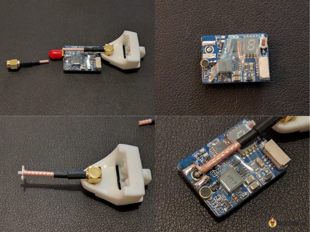
Having soldered the ESC signal wires, camera signal wire and VBAT, RSSI, CURR, 5V between the PDB and FC, it was time to decide which length of VTx wire I’m going to use. Turned out that the only suitable place for the VTx is right on top of the ESCs in the back of the quad. 5cm coax extension cable was too long and I decided to remove the connector, and solder it directly to my VTx. But just before that, let’s try mounting the SMA connector to the antenna holder.
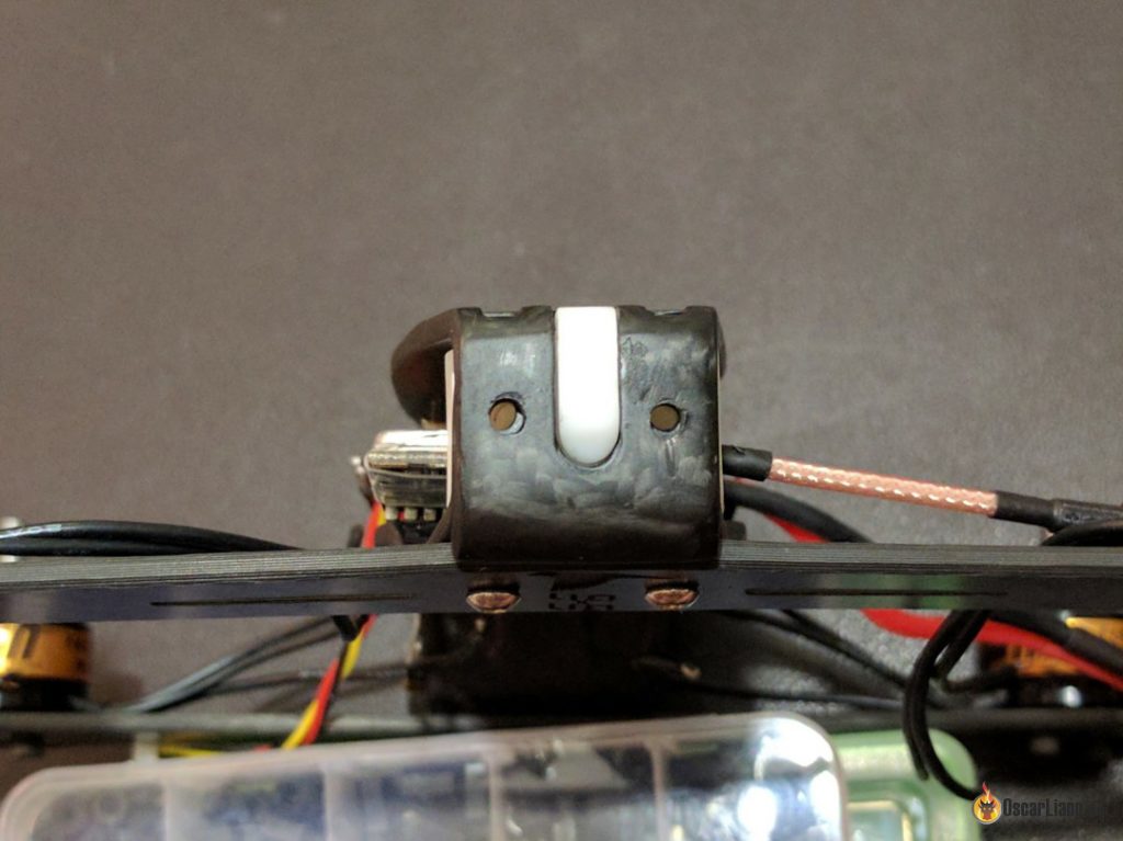
Something’s wrong, this coax shouldn’t bend like that and has likely suffered structural damage during this procedure. Also, why there’s a hex notch at the bottom and not on top? It looks designed for a SMA retaining nut, but being on the wrong side it’s pointless.
Sparrow Knight R220 creators specifically recommended using a right-angle SMA extension, but my version of the holder doesn’t allow screwing it in without damaging the coax. I’ve heard they have fixed this issue in further revisions.
At this point I decided to assemble the frame just to test how it sits with the antenna holder in place. Doing so you can see the holes are misaligned in the back of the frame. You can also see the carbon looks a bit weathered.
Then I had to take the frame apart, and here comes the little trick mentioned by Warrick Dainter but not mentioned in the manual.
Two parts of the frame are held together very tightly, with antenna holder acting as a lock, and the easiest way to disassemble it is by sticking a flat screwdriver between two plates in the back to pull them apart. After that I could separate them with my bare hands, although first time it was a bit scary and it felt like I was going to break something. I had to perform this procedure multiple times while writing this review.
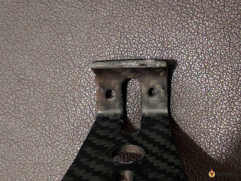
At some point my SMA connector had fractured due to the top plate touching it during assembly sometimes. Also, a small hollow uncovered on the edge of top plate. I wonder whether there are other hollows in the middle section of frame.
Back to the subject of VTx, I decided to place it right next to antenna holder with minimal coax length.
Looks good as new :-)
The radio receiver I’m using is XSR, and while I could back-feed RSSI from my transmitter via telemetry, that wouldn’t help the RROSD which expects analog signal for RSSI.
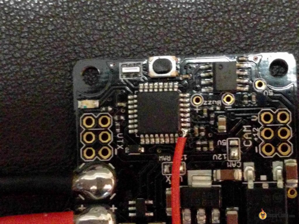
Luckily, there’s a pad on the XSR which provides RSSI. I decided to make it as neat as possible and route RSSI through the unused CPPM pin of Rx connector. The general idea is described by J. Blackman in his blog.
I had to remove a resistor and a capacitor to decouple CPPM output from the CPPM pin, and run a jumper wire from RSSI pad to the CPPM connector. Having no transparent heatshrink at my disposal I decided to perform a surgery :-)
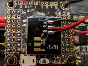
Soldered the LED board. I decided to drive it from VTx 5V output. Please note that these LED boards require a very specific DIN and VCC relative levels in order to function properly, if your 5V reg outputs slightly more than 5V your LED may not work at all. Luckily, my VTx outputs 4.9V which works OK in conjunction with 3.3V DIN from FC.
Added some wire mesh sleeve for the polished looks. Time to assemble the frame again.
Tightening rear screws turned out to be problematic due to displaced holes, eventually I had to drill the left one and discover that the M3x16 screws are 1mm longer than necessary and screw directly into the capacitor on LED board, shortening and damaging it. I had to replace this SMD cap with a similar one.
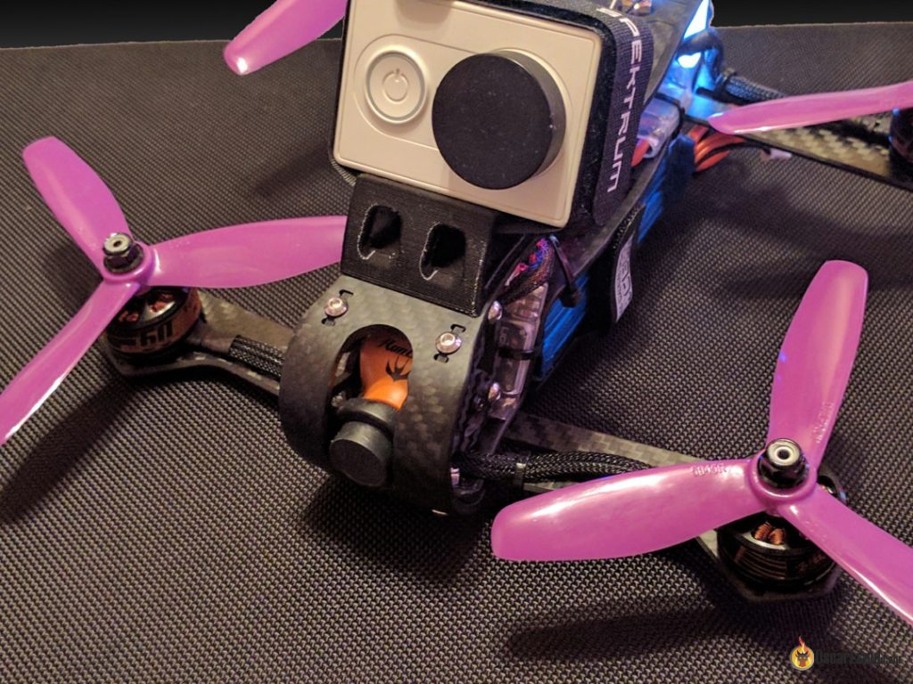
Finally, here’s the result! I could forgive most of the issues I had during building this awesome neon glow. Unfortunately it’s snowing where I live right now and I couldn’t capture good footage from the maiden, camera lens got covered in snow on takeoff :-) I will post more photos and videos as soon as it gets a bit less snowy.
Bottom line
The quad weighs 460g without an HD camera and a battery. With a Dinogy 1500mAh 65C battery and Xiaomi Yi it weights 695g, which is quite heavy, but mostly related to the heavy ESCs and motors I am using. Assembled frame is stiff and does not exhibit vibrations, it’s pretty easy to tune with BetaFlight 3.1 and flies nicely even at default PIDs. F60 are probably a bit too heavy and I’m going to try F40PRO when they arrive.
Adjustable camera angle is a nice feature, but I don’t see myself changing it too often. Frame allows mounting all the electronics inside for better protection, but space is extremely tight and it’s an exercise in discipline.
Upon final assembly of Sparrow Knight R220, I noticed that my FC stack does not allow the removal of HD camera holder, without taking the frame apart. What a bummer.
The 3D printed HD camera mounting plate holds my Xiaomi Yi nice and snug with a velcro strap, bayonette-like design allows mounting different accessories, you could even DIY them if you’re lucky to have a 3D printer. InventorFPV promises a variety of accessories available from their store in the future. Also, there were rumors about thicker spare arms available.
Pros
- Unusual, futuristic design
- Adjustable camera tilt
- All electronics fit inside
- Awesome light shell visible both in daylight and at night
- Camera-mounting accessories
Cons
- Weight – 150g frame
- Design and manufacturing flaws which complicate the build process
- High Price








2 comments
Did I miss something or was there no mention of the fact that this thing has 5 motors?
So jealous been waiting for the cash to buy one… still waiting lol by looks gorgeous.