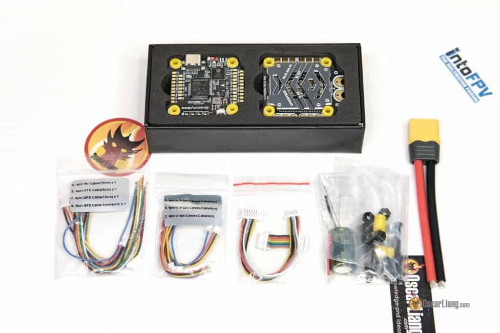
The F7 V3 is Speedybee’s premium FC stack offering, at US$119.99 for the whole stack, or US$62.99 for the FC. Let’s compare the F7 V3 stack to the F405 V3 which I believe to be the best value stack in 2022, and see what benefits it gives you from spending the extra $50.
New to FPV? Check out my flight controller buyer’s guide.
Table of Contents
Where To Buy?
Update (27 Sep 2023): NEW VERSION, the F405 V4 is here.
Stack: Speedybee F7 V3 FC + 50A BLHeli_32 4in1 ESC
- GetFPV: https://oscarliang.com/product-hjay
- AliExpress: https://s.click.aliexpress.com/e/_Dkisdd1
- RDQ: https://oscarliang.com/product-j7qh
- Amazon: https://amzn.to/3f3ABGe
- Speedybee: https://oscarliang.com/product-rd5o
Just the FC: Speedybee F7 V3 FC
- GetFPV: https://oscarliang.com/product-9l77
- RDQ: https://oscarliang.com/product-dslm
- NBD: https://oscarliang.com/product-up2q

- 1 4-Pin SH1.0 to SH1.0 Analog VTX Cable 60mm – Yellow and Blue
- 1x 6-Pin SH1.0 GPS module Cable without connector – 100mm
- 1 4-Pin SH1.0 to 3+ 2-Pin JST1.25 FPV Camera Cable – 30mm
- 1 4-Pin SH1.0 to 3+ 2-Pin JST1.25 FPV Camera Cable – 60mm
- 1 4-Pin SH1.0 to 4-Pin JST1.25 FPV Camera Cable – 60mm
- 1x 6-Pin SH1.0 GPS module Cable with connector
- 1 4-Pin SH1.0 Radio Receiver Cable – 100mm
- 1x SH 1.0mm 8-Pin Cable -30mm
- 5x M3 8mm Silicone Grommets
- 1x DJI 6-Pin Cable – 80mm
- 1x 35V 1500uF Low ESR Capacitor
- 1x SH 1.0mm 8-Pin Cable -30mm
- 5x M3 8.1mm Silicone Grommets
- 5x M3 Silicone O-Ring
- 5x M3 30mm hex screws for stack
- 1x XT60 Power Cable
Specifications
SPEEDYBEE F7 V3 FLIGHT CONTROLLER
- Betaflight Firmware Target: SPEEDYBEEF7V3
- MCU: STM32F722
- IMU (Gyro): BMI270
- Supports BetaFlight OSD in Analogue FPV system thanks to the AT7456E chip
- Onboard BMP280 barometer
- 500MB onboard flash memory for Blackbox
- Power Input: 3S – 6S Lipo
- USB Port: Type-C
- BEC: 5V@2A, 2x9V@2A, 3.3V@500mA
- Built-in Bluetooth and WiFi for firmware configuration and flashing wirelessly via Speedybee APP
- I2C Supported. SDA & SCL pads on the front side. Used for magnetometer, sonar, etc.
- Supported Firmware: BetaFlight, EMUFlight, INAV
- 8 Motor outputs (ESC signals)
- 4 full UART’s + a half UART (RX4, dedicated for ESC telemetry)
- Mounting: 30.5×30.5mm, 4mm hole size
- Dimensions: 41(L) x 38(W) x 8.1(H)mm
- Weight: 9g
SPEEDYBEE 50A BLHELI_32 128K ESC
- Runs BLHeli_32 Firmware
- Onboard Current Sensor (Scale=490 Offset=0)
- Current Rating: Continuous 50Ax4 (Burst 55A 5 seconds)
- Power input: 3S – 6S LiPo
- Mounting: 30.5×0.5mm, 4mm hole size
- Dimension: 45.6(L)x40(W)x8.8mm(H)
- Weight: 19.2g with heatsink
Closer Look at the Speedybee F7 V3 FC/ESC Stack
Compared to the Speedybee F405 V3 FC, the F7 V3 is powered by a faster processor (F722’s 216MHz vs F405’s 168MHz), but it has less memory (F722’s 512kb vs F405’s 1Mb) which affects the longevity of the F7 V3 (how long it may be supported by Betaflight if the code size gets too large). But as for now both of these processors are great for the current version of Betaflight.
The F722 is fast enough to allow 8KHz PID Loop Frequency while the F405 can normally only run 4KHz. However, due to the BMI270 Gyro used in the Speedybee F7 V3 FC, the PID Loop Frequency is limited to 3.2KHz, so the speed advantage of the F722 processor isn’t as meaningful on this board.
There are 4 full UART available (plus a half UART – RX4 dedicated for ESC telemetry), these UART can be used for connecting your receiver, VTX (SmartAudio), camera (UART control), GPS etc. And it uses USB-C connector which is more robust and easier to plug in than Micro USB.
Just like the F403 version, there is a 22mm wide cutout in the front of the FC, which is to leave room for the FPV camera in certain tight frames which is a thoughtful feature. The F7 V3 also has great layout and easy to solder pads. All the pads are clearly labelled.

There are 8 motor outputs (M1-M8) which allow you to use this FC on an hexacopter or octocopter.
There’s an OSD chip onboard, so it supports digital as well as analog FPV system. There is a barometer onboard, not often used in Betaflight but need it or not, it’s good that it’s there.
Something I have not seen before on an FC is the battery indicator (4 LED’s), which shows the voltage level of the LiPo plugged in.
However, there are several features in the F7 V3 FC, that the F405 V3 FC does not have:
- Double 9V BEC providing a total 4A output on the F7 vs 2A on the F405
- An insane 500MB Onboard flash memory for Blackbox logs! (typically FC only comes with 16MB flash) That’s enough storage for over 3 hours of flight logs! You don’t need to worry about running out of memory probably for a whole day of flying
- Apart from having Bluetooth, it also has WiFi which means it supports firmware flashing wirelessly. It basically has the Speedybee Adapter 3 built into the FC! Adds $30 value to the stack if you don’t already have this adapter
Although BLHeli_S ESC are cheaper and have almost the same capability as the more expensive BLHeli_32 counterpart, there’s something BLHeli_S can’t do.
BLHeli_32 allows you to set a much wider range of PWM frequency (between 16KHz to 128KHz, “byRPM” as well), the BLHeli_S version can only run fixed a fixed value between 24KHz and 48KHz. Therefore, BLHeli_32 can arguably offer more balanced performance – higher torque at low throttle while running smoother in higher RPM thanks to the variable PWM Frequency.
There’s a heatsink on the ESC to keep it cool and potentially shield some of the interference from the FET’s.
How to Use
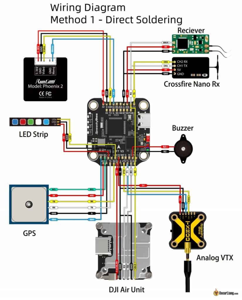
Here are the wiring diagram using the connectors, or direct soldering.


The plug for the analog VTX only supply 5V, which seems to be designed for Speedybee’s own TX800 VTX. I wish there’s a solder bridge you can select between 5V and 9V or even VBAT.
If you are pairing the F7 V3 FC with the SpeedyBee BLHeli_32 50A ESC, make sure to set the current sensor scale to 490 and Offset 0.
Unlike most other FC, the onboard 500MB memory chip for blackbox on the SpeedyBee F7 V3 is configured as an SD Card, which means you won’t get the option to erase its content like a data flash chip. Your only option to erase it is to activate mass storage, then either manually delete the files under the LOGS folder or format the drive as FAT32.
Official manual provided by Speedybee: https://store-fhxxhuiq8q.mybigcommerce.com/product_images/img_SpeedyBee%20F7V3_STACK/20220926F7_V3_Stack_Manua_EN.pdf
Build Log
This stack is going into my next build. I will be sharing the build log in the next week or two along with some PID/filter tuning guide.


20 comments
Hola
Alguien sabe donde estan las uarts 4 y 5 en la FC F7 V3 50A?
Yo localice las 1-2-3 y 6 pero las otras no
gracias
Can you recommend a GPS module that uses the connector?
Is the connection for ppm same as sbus receiver? And is the connection for crossfire same as elrs?
Connections for Crossfire and ExpressLRS are the same. But it’s different for PPM and SBUS – yes they both require just one signal wire, but they need different pads. For PPM you need a PPM specific pad, for SBUS you can use a serial port (only the RX pad). PPM is such an oudated protocol, most FC don’t support it anymore though you might be able to remap some pads to support it.
Please Help.
I have just soldered my Speedybee F7 V3 Stack, when I power it up the motors makes initial beeps but when I try to test tem they are not spinning at all. Also tested via BlheliSuite with same result. FC is flashed with BF 4.5.0 and the ESCs are flashed with 32.10
I got the same issue on the same setup – all the motors are beeping correctly (three times, then two) but not spinning – not from Betaflight configurator, nor from BLHeli Suite (via Betaflight Passthrough).
It seems the issue is in Betaflight 4.5.0. It started working when I downgraded to Betaflight 4.4.3.
BLHeli rev. 32.10 works fine.
maybe it’s related to this issue: https://github.com/betaflight/betaflight/issues/13598
Does it have a PINIO support for turning on off VTX power like it was in MATEKSYS F722 SE ??. Digital VTX goes really hot fast so it would be nice to have an ability to turn it on and off using defined radio chanell
No it does not.
The log files in the blackbox LOGS folder are 0 bytes. With the other folder names and oddball files that show up in Mass Storage device mode I am lost to the reason the logs are created but no info is logged. Can I Format the MSDevice and not lose other functionality?
I built this using all connectors. had to desolder and resolder the pinout on the wiring end of my GPS module so the connector end matched the FC pinout.
Just finished working out the kinks in GPS RTH AUTO LAND but now 4.4.2 has released so we’ll see.
About the URART 5 for ESC telemetry I was curious is there anything I can do to enable an OSD element to get say ESC Temp working?
I set up my elrs receiver on this board and plugged it into the 4v5 pad as shown on diagram however my reviever wont connect when using usb. reciver light is on but no data to set up flight modes.. when connecting battery, the reciver then binds. and i can use usb to connect to betaflight to set up flight modes. but usb alone not working… are you sure it goes on the 4v5 pad?
check voltage with a multimeter see if you get 4V5 when connected USB.
Heya, how did you get usb working? I can’t get it to ping at all. Just acts dead. BT works though
Just got this with the hope of putting it in an Impulse RC Apex 5 inch. Note the stack screw’s on the apex are barely large enough to hold this stack, might need smaller rubber grommets smaller nuts to hold in the stack screws Looking for somewhere to get longer stack screws also.
I fly this stack in a 5″ copter with no problems, however in a 7″ setup with big 6s Lipos (4000mAh and 5800mAh) I burned 3 of the SpeedyBee F722 FCs so far (once it also killed the GPS module and the ELRS-receiver).
It seems that the 5V onboard BEC/PDB circuit is too weak.
Does somebody has experienced similar problems with this FC or can share some insights/analysis of the onboard PDB?
I just got this stack. I really love it but I am having trouble with the current measurement. Does anyone have a problem with it or just a faulty unit?
What do you mean by troubles with current measurement? I have troubles also – meaning I cannot measure higher values, than about 66A. Is it that issue? Have you any solution yet?
HELLO, do you know where is the 5v BEC Oon the fc? mine has burned and i would like to desold this bec in order to add an external 5v BEC
Thanks to have specified the FAT 32 format of the “SD Card” of this board, I have formatted it into Fat and it jammed with unknown files badly.