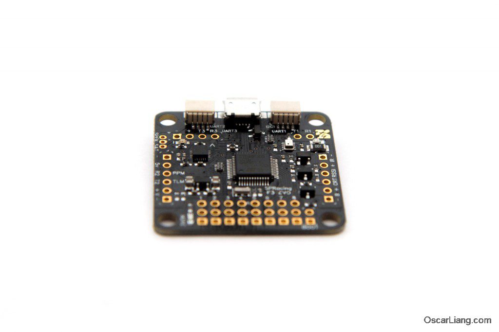
Seriously Pro (SPRacing) released a new F3 flight controller, the EVO. In this tutorial we will walk you through the process to set up this FC.
The SPRacing F3 EVO is an affordable flight controller yet full of awesome features. It’s designed for the familiar Cleanflight, and supports all the latest Cleanflight features. For the most part, this flight controller set-up is very similar to others I’ve used in the past.
What attracted me to this controller?
- Built in transponder for racing (lap time recording)S
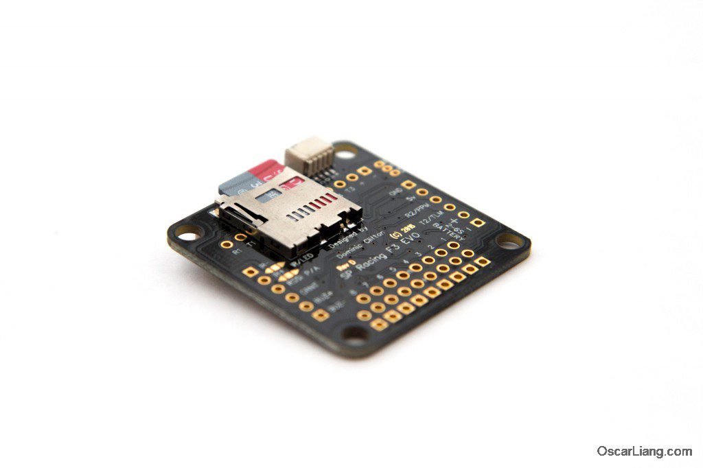
- Built in Micro SD Card Recorder for saving Blackbox logs (Super long recording time and much faster data export)
- STM32 F3 Processor
- 3 UART’s (hardware serial port with built-in inversion)
- Affordable price
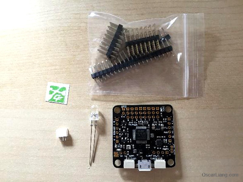
What comes with the flight controller?
- SPRacing F3 EVO flight controller
- IR LED Transponder
- 90 degree header pins and Straight header pins
- Cleanflight sticker
- Spare JST-SH socket
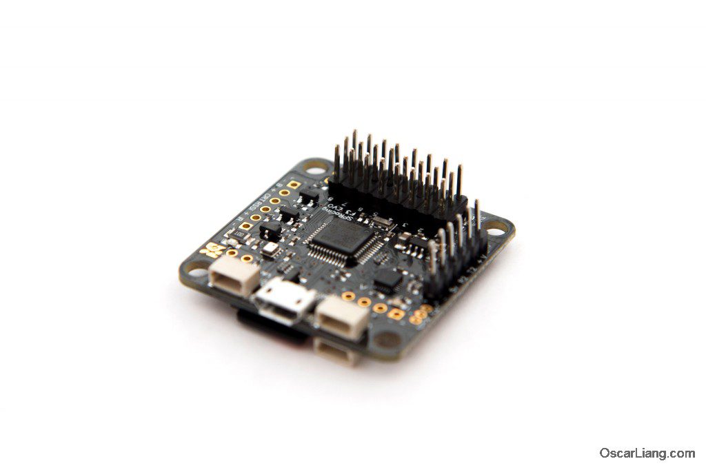
1) Soldering the header pins
Installation was very straightforward.
I am going to swap out the old dead flight controller from one of my existing builds, to make way for the new one. I am installing this FC on the TSX220 frame, which is quite tight for space, so I decided to use the straight header pins, as right angle pins will protrude too far out for my liking.
2) Decision: IR transponder or RGB LED?
I have this listed as point two, because this is something you absolutely need to decide before you start tucking this away in to your frame. On the back of the EVO board, you need to bridge a solder joint which will let you select either to run IR LED as a racing transponder, or to drive normal Programmable RGB LEDs for aesthetics or visibility to other pilots.
In this configuration, I’ve selected the IR Transponder by bridging the LEFT pointing arrow and the square in the middle.
If you select the RIGHT pointing arrow and middle square, it can be used to drive normal LEDs (such as WS2812). I suspect most buying this board will be using it for the racing transponder capability.
DO NOT solder all 3 points.
The second thing you need to consider when installing the transponder IR LED, is whether to solder it directly on to the FC board, or to solder some pins in then run wires from them.
I’d recommend not soldering it directly to the board, the reason is fairly simple. If you’re at a race and the transponders receivers are on one side, your LED might not have a good line of sight with those. If it’s on a wire, you can select which side of your craft is best, as each race the setup could be different.
3) Configure the transponder in Cleanflight
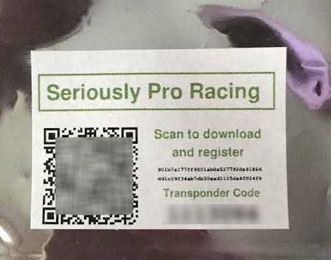
When I received my flight controller, it came in a small package that had a sticker with a QR code on the front of it. This code is IMPORTANT, it’s used to generate a unique transponder ID.
Rather oddly, there doesn’t appear to be a means to register this code to get your transponder ID without using a QR code reader. I tried putting the URL in manually but it just didn’t work.
There are a number of free QR code readers available for both android and iOS (Apple) systems. Simply scan the QR code using your smart phone (the square bar-code like thing on the left) and it will load the seriously pro website, which will churn out what to me looks like a hexadecimal code.
Here is showing where to input the transponder code in Cleanflight configurator.
Put the 12 digit alphanumeric code in to the box shown above in cleanflight, hit save and you’re good to go.
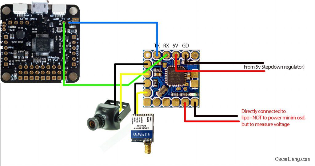
4) Wiring diagram
Wiring is a fairly standard affair, which lines up with previous seriously pro boards.
Just remember, the board cannot be powered directly from the LiPo like say, a dodo can. You need to step the voltage down to 5V like you would for a Naze32. I’ve shown a pololu step-down voltage regulator directly connected to the 4 cell lipo in this case. If your ESCs have a built in BEC (becoming less common now it seems) you can use only ONE of those ESCs to power your board.
Remember to disconnect the RED (positive) wire from the other 3 ESCs, otherwise bad things will happen.
Connecting the X4R
I’ve shown the board connected to an X4R receiver. To get this to work, one must change a couple of things in cleanflight.
- Go to Ports tab and under UART2, turn on SERIAL RX
- Hit Save and Reboot
- Go to the Configuration tab
- Select RX_SERIAL and SBUS
- Hit Save and Reboot
Once rebooted, you need to go to the Receiver tab in cleanflight. I had to change my receiver mapping to TAER1234. Once that’s done, moving the sticks on your transmitter should result in the bars moving around correspondingly.
5) OSD – MinimOSD Setup
I have a Micro MinimOSD connected to my EVO F3 board so I can keep an eye on battery voltage, which is all you need really.
Check out this MinimOSD tutorials, to get familiar with the software software and the connection.
The TX and RX pads on the OSD go to R1 and T1 respectively on the SPRacing EVO FC. If you do it the other way round, the OSD will not be able to display the telemetry.
6) Blackbox
Another feature of this board that attracted me to it in the first place, was the possibility to use a large capacity micro SD card (such as 32GB) to log all my flights. You can record all day long and it will not run out of memory.
You can use the flash memory on some FC, but the biggest you can get is only about 16MB. Not to mention it takes “forever” to export the blackbox data from it! (5 mins for 1 min flight?)
First of all, enable black box recording in cleanflight
On your microSD card a filed called FREESPAC.E will be created. Don’t mess with this. From the official cleanflight documentation:
The first time you power up Cleanflight with a new card inserted, the flight controller will spend a few seconds scanning the disk for free space and collecting this space together into a file called “FREESPAC.E”. During flight, Cleanflight will carve chunks from this file to create new log files. You must not edit this file on your computer (i.e. open it in a program and save changes) because this may cause it to become fragmented. Don’t run any defragmentation tools on the card either.
You can delete the FREESPAC.E file if you want to free up space on the card to fit non-Blackbox files (Cleanflight will recreate the FREESPAC.E file next time it starts, using whatever free space was left over).
The maximum size of the FREESPAC.E file is currently 4GB. Once 4GB worth of logs have been recorded, the FREESPAC.E file will be nearly empty and no more logs will be able to be recorded. At this point you should either delete the FREESPAC.E file (and any logs left on the card to free up space), or just reformat the card. A new FREESPAC.E file will be created by Cleanflight on its next boot.
On the SD card, there will be a folder called ‘logs’ and in there will be all your logs. Remember that depending on your looptime, the file size will be different: the lower looptime, the larger the file will grow when you are recording.
You can use the blackbox explorer to view these files.
So, you have a bunch of logs – what do you do with them?
The first thing I’d do is subscribe to Joshua Bardwell’s excellent youtube channel. He frequently analyses logs of his subscribes flights, in great detail. However, he stresses this often – if your craft flies well already, but you’re not happy with your traces, don’t get fixated on that fact that your traces aren’t perfect.
Another thing you can do is to get advice on PID tuning, by submiting your flight logs and CLI Dump on IntoFPV forum: http://intofpv.com/forum-tuning-clinic
ESC Flashing and Programming
Does pass-through work on the EVO FC? (flashing BLHeli firmware and change settings via flight controller) The answer is YES!
You just need to download the latest BLheliSuite (14.4 Beta as on 19th April).
Credit
This article is written by Goonage, please check out to his channel ! :)







44 comments
spracing f3 EVO FC led transponder solder_bridge
If you select the RIGHT pointing arrow and middle square, it can be used to drive normal LEDs (such as WS2812). I suspect most buying this board will be using it for the racing transponder capability.
There is NO right pointing arrow in the picture?????????
Thanks,
Stan
By “right pointing arrow”, we are referring to the solder pad on the right, that you need to bridge with the middle pad.
It kind of looks like the arrow :)
How connect Fs x6b to f3 evo, ibus?
How connect sonar to sp r f3 evo?
Hi Oscar and Dominic,
I have SP F3 EVO on 500 X frame(like flamewheel), RCtimer SimonK 30A ESC with RCTimer HP2212-1000kv motors and 10 inch props, and Tx Rx Quanum i8 powered by 5000 mAh battery(3S overlander). My problem is that when I put all together, always one motor is jerking until I give it full throttle and then it starts working as it should. I got it flying only once and never again. ESCs are calibrated directly via throttle channel.
regards Luka
Hi Oscar, hi Dominic,
i have an SPF3Revo and an TrampHV and im questionning about VTX slider in configuration that can make TrampHV configurable via transmitter.
but where i need to connect the TrampHV to the SPRF3evo ?
thanks for help.
Thanks for the excellent info Oscar.
I have an X4R connected as you do, but don’t see any telemetry data (i.e. cellSum battery voltage). How do I connect or configure to obtain this data?
You need to connect Smart port from RX to FC
Can I use other pdb than sp pdb/OSD?
did you notice any problem with a gyro ? i goot secoond sp reacing f3 evoo (first is for brush motors) and gyro is dead – no reading – after some shaking and ratotion i found a few readings – if you can gimme any advice to email please
hi can you connect sonar to this board?
thanks
This board is designed for drone racing :)
Hey Oscar, really love your blog! Great job.
Do you have any plans on writing an article about the new SP Racing F3 OSD/PDB in combination with their F3 Evo FC?
I experience problems with connecting the PDB to FC over UART1 and using FrSkys Telemetry on UART3. I think both connections need MSP activated what is not possible within Cleanflight…
sorry no plan of using their products, maybe get in touch with their support.
I got a diatone gt2 200 with a sp racing f3 board and the sp3 vtx with osd. My question is, is there a current sensor on the fc that I can use for read out on the osd or does the vtx have to have the current sensor. I can’t seem to calibrate the current reading.
there is no current sensor on the SPR F3 FC, you will need an external current sensor, or a PDB that comes with integrated current sensor.
I set up a speed addict superlight with the evo and I’m experiencing a glitch twitch in all modes. Motors are in sync with the master in blheli. throttle min wont change in cleanflight for some reason and it’s set to 1150 . I flashed beta hoping it would magically fix but now my com port 4 is recognized. I’ve gone through the zadig and still no luck. Argh. Any suggestions?
So I just got the sp f3 evo and I’m not sure if It already has the correct firmware loaded on to the board. I was able to connect to it and program it with clean flight. But for some reason my accelerometer was wigging out,or the mag but it was level but for some reason it cept yawing to to the left and right in the setup tab in clean flight. The board USB is on the left side of my qaud.
does it yaw very slowly? if so that’s normal.
Im experiencing the slow yaw as well. Is there a way to change that?
Hi! Could you help me with choosing appropriate buzzer for this fc? Also, how to configure it?
Thank you!
any passive 5V buzzer should work fine. there is no configuration required, for buzzer to work, just need to hook it up. However it depends on what you want to use the buzzer for, you need to turn those features on in the software, like lost model buzzer, VBAT etc.
Hi!
What is IR Transponder used for?
Thank you
for recording lap times in races :)
It sends out a signal like a TV remote control.
The common timing system used for racing uses IR receivers at the start gate to time laps as quads go through.
Hi Oscar!
I bought a QX95 that uses SP RACING F3_EVO_Brush Flight Control and I’d like to connect micro minimOSD…. Do you thing I should connect minimosd TX and RX at UART1 R1 and T1 of this board?
This is the board picture: img.banggood.com/thumb/water/oaupload/banggood/images/66/8E/26ad64ce-a312-482c-91ec-4d7f7c6321e7.jpg
Thank you!
yes that right, and don’t forget to enable MSP in the port tab in cleanflight for UART1
If I bougth a clone SPF3EVO will i be able to get the transponder working with out that qr code???
No.
thanks for all the god info and advice that you put out there,you´re tutorials are very well explained.thanks for that!
nevermind,i fixed the problem,it seams that with version mw.1.5 it´s working ,reflashed and now everithing it is like it should.thanks
hy,i connected the minim osd exactly like in the diagram above,but i have only baterry data,it is showing always disarmed and does not receive anything else,it is not the first minim osd that i have,i had others with racing f 3 deluxe,so i know how to make all the conections and how to flash the firmare,i have mw 1.6 on it.normaly i use it with horizon and throtle pozition,but ia have only batery,any sugestions will be apreciated,thanks
Hi,
I have the same problem. Did you solved it?
Thanks!
I was going to use the Full naze32 board on my 500 Vtail but a board that small just doesn’t look good in a 500 frame. I went with the kk2 board instead and install the naze on a robocat 270.
I tried to boot load Cleanflight and now my evo wont power on at all. I used the usb to down load, what did i do wrong.
did the solder accidentally spill on the board and shorted some of the pins/chips? inspect carefully
I sent the board back and after thier inspection it was concluded that nothing was wrong with the board. I found out that I needed to install a usb driver to support communication between the PC and the board.
How to set up the SPRacing F3 Evo with an Spektrum receiver? Do you already have an tutorial for it ?
sorry i personally don’t use Spektrum stuff… currently only using Frsky system..
If you are referring to Spektrum Satellite receivers then yes, SP Racing F3 Evo directly supports this. You just need to wire the three connectors on the FC to your satellite receiver. Go to cleanflight and in the “receiver mode” select RX_SERIAL; in “Serial receiver provider” select either SPEKTRUM1024 or SPEKTRUM2048. Normal Spektrum DSMX satellite receivers work on SPEKTRUM2048.
If you are referring to Spektrum PWM or PPM. The answer is still yes. For PWM, you need to connect your PWM signals to their respective pin connectors. For PPM, there is a PPM pin located at the bottom board with mark “R2/PPM”.
where do you connect the 3 spektrum sat wires on the flight controller? Ive heard mixed answers
Hi im having same trouble, with my dx6i and qx70
Can i used this board on a 500 vtail.
Yea it should work :)