Today, we’re diving into the world of MOSFETs and how to use them in your electronics projects. As a non-academic hobbyist myself, I’ll break down the concept into simpler terms and focus on the practical applications that matter to you.


But don’t worry, if you’re curious about the nitty-gritty details of how MOSFETs work, I’ll share some valuable academic articles and resources at the end of this post. Keep in mind that MOSFETs have their own set of pros and cons when compared to BJTs, so choose wisely based on your specific needs.
For your electronics projects, you can grab some MOSFETs here:
- Amazon: http://amzn.to/2Gk6ruW
- AliExpress: https://s.click.aliexpress.com/e/_DmS90pT
Table of Contents
What is MOSFET?
MOSFET, short for metal-oxide-semiconductor field-effect transistor, is a unique type of field-effect transistor (FET). Unlike a bipolar junction transistor (BJT) that operates based on current control, MOSFETs are voltage-controlled devices.
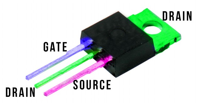
The MOSFET has 3 terminals, “gate“, “drain” and “source“, differs from BJT which has “base”, “collector”, and “emitter” terminals. By applying voltage to the gate, you create an electrical field that controls the current flow through the channel between the drain and source, without any current flowing from the gate into the MOSFET itself.
Think of a MOSFET as a variable resistor, where the voltage difference between the gate and source determines the resistance between the drain and source. When no voltage is applied between the gate and source, the drain-source resistance is incredibly high—almost like an open circuit—preventing current from flowing. However, when you apply voltage to the gate-source, the drain-source resistance decreases, allowing current to flow through the now-closed circuit.
In essence, the gate-source voltage applied to a FET controls the electrical field across a channel, similar to pinching or opening a straw to stop or permit current flow. This property makes FETs ideal for handling large current flows, and MOSFETs are commonly employed as switches.
To sum up the distinctions between BJTs and MOSFETs:
- MOSFETs are voltage-controlled, while BJTs are current-controlled. When using a BJT, the base resistor must be carefully calculated based on the current being switched. However, with a MOSFET, simply apply enough voltage to the gate, and the switch operates.
- MOSFETs have very high input impedance, which means almost anything can drive them.
- MOSFETs exhibit high input impedance, making them versatile and adaptable to various applications.
How to Use MOSFET as a Switch
To use a MOSFET as a switch, you need to ensure that the gate-source voltage (Vgs) is higher than the source voltage. When the gate is connected to the source (Vgs=0), the MOSFET remains off.
Take the IRFZ44N, a “standard” MOSFET, as an example. This MOSFET only turns on when Vgs ranges between 10V and 20V. However, it’s common practice not to push it to the limit, so Vgs values of 10V-15V are typically used for this type of MOSFET.
If you’re planning to drive the MOSFET using an Arduino operating at 5V, you’ll need a “logic-level” MOSFET capable of turning on at 5V (Vgs = 5V), such as the ST STP55NF06L. You can find it here:
- Amazon: https://amzn.to/3TGvxYh
- AliExpress: https://s.click.aliexpress.com/e/_Dk2FN9r
Additionally, you should include a resistor in series with the Arduino output to limit the current. The gate’s high capacitance can draw a significant instantaneous current when attempting to turn it on. A 220-ohm resistor is a suitable value for this purpose.
For a more technical explanation of how a MOSFET functions as a switch, consult this page. If you’re interested in more advanced MOSFET applications, visit this page. Remember to always choose the right MOSFET and configuration based on your specific project requirements.
Understanding Different Types of MOSFETs
MOSFETs come in various types, each with unique characteristics. To understand them better, we can categorize them into three main groups:
- N-Channel (NMOS) or P-Channel (PMOS)
- Enhancement or Depletion mode
- Logic-Level or Normal MOSFET
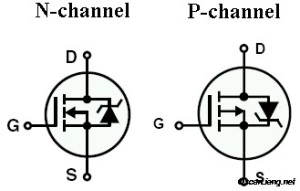
N-Channel (NMOS) – In an N-Channel MOSFET, the source is connected to ground. To turn the MOSFET on, the gate voltage must be raised. To turn it off, the gate should be connected to ground.
P-Channel (PMOS) – For a P-Channel MOSFET, the source is connected to the power rail (Vcc). To allow current to flow, the gate needs to be pulled to ground. To turn it off, the gate should be pulled to Vcc.
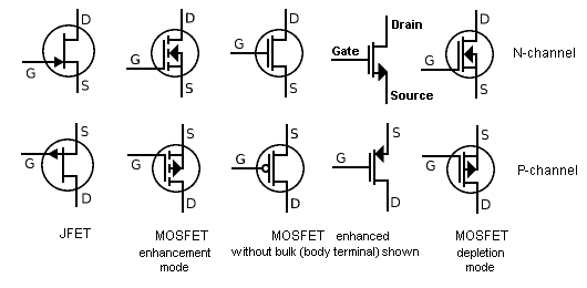
Depletion Mode – This type of MOSFET requires a gate-source voltage (Vgs) to be applied to switch the device “OFF.”
Enhancement Mode – In contrast, enhancement mode MOSFETs need a gate-source voltage (Vgs) applied to switch the device “ON.”
Out of all these types, the most commonly used is the N-channel enhancement mode MOSFET.
As for Logic-Level and Normal MOSFETs, the primary distinction lies in the gate-source potential level required to drive the MOSFET. Logic-Level MOSFETs can be driven with lower Vgs values, making them suitable for microcontroller applications, whereas Normal MOSFETs typically require higher Vgs values for operation.
A Simplified Explanation of How MOSFETs Work
In this section, I’ll provide a straightforward explanation of how MOSFETs work, without delving too deep into technical details. For more in-depth information or if you have any doubts, please refer to the references and links provided at the end of this post.
MOSFETs are voltage-controlled field-effect transistors that are different from JFETs. The gate electrode in a MOSFET is electrically insulated from the main semiconductor by a thin layer of insulating material (typically silicon dioxide, which is similar to glass). This insulated metal gate functions like a capacitor plate and results in an extremely high input resistance (almost infinite). Since the gate is insulated, no current flows into the MOSFET from the gate.
Applying voltage at the gate alters the width of the drain-source channel, which is the path along which charge carriers (electrons or holes) flow. The wider the channel, the better the device conducts.
MOSFETs are used differently compared to conventional junction FETs:
- Their incredibly high input impedance makes them useful for power amplifiers. Additionally, MOSFETs are well-suited for high-speed switching applications. Some integrated circuits contain tiny MOSFETs and are used in computers.
- However, the thin oxide layer also makes MOSFETs susceptible to damage from built-up electrostatic charges. In weak-signal radio-frequency work, MOSFET devices generally don’t perform as well as other types of FETs.
Frequently Asked Questions
Where should the load be connected to a MOSFET, Source or Drain?
For an N-channel MOSFET, it’s common to connect the load to the Drain side, as the Source is usually connected to ground. If the load is connected to the Source side, a higher Vgs will be required to switch the MOSFET, resulting in less current flow between the Source and Drain than expected.
Is the heat sink connected to the Drain?
Typically, the heat sink on the back of a MOSFET is connected to the Drain. If you mount multiple MOSFETs on a heat sink, they must be electrically isolated from the heat sink! Regardless, it’s good practice to isolate the MOSFETs to prevent any issues if the heat sink is bolted to a grounding frame.
What is the purpose of the Body Diode?
MOSFETs have an internal diode, known as the body diode, which can sometimes allow unintentional current flow. The body diode can also limit the switching speed of the MOSFET. However, if you’re operating under 1MHz, you generally don’t need to worry about the body diode.
Resources
- Theory behind MOSFET (Youtube Video Lecture)
- Understanding Modern Power MOSFETs
Edit History
- Oct 2013 – article created
- Mar 2023 – revised
47 comments
great but how to connect a mosfet where goes + and where goed – and a adruino
Hi,
Can you connect sixteen 1200 V MOSFETS in series (All of them driven with individual isolated gate drives which are synchronized) in a 11 KV circuit? If so will it be necessary to have balancing resistors (16) connected across each MOSFET? What kind of surge protection will be required if the load is inductive?
thanks and kind regards,
Job
I enjoyed the simplicity in which the article was written. Thank you very much.
Very helpful….I have been out of electronics for a long time and just started up again and it’s literally a new world. I don’t remember MOSFETs being around, or at least prominent, back then. This was extremely informative. Thank you very much.
Lesson is very easy and very nice for understanding .
I have never read such a good article regarding MOSFETs.
Thanks for the article – well done.
I would like a Mosfet to act like a Latching relay. It will be switching 220V AC and acting as a light switch. Powered from a battery operated Arduino. So current should only be drawn when latching on or off, not when energised. Is a Mosfet capable of this – thanks in advance.
I’m a novice with MOFSETs. struggling to determine if a circuit I’m working on is feasible. I’m designing a board that uses an ESP-32 micro controller (3.3v). I’m using a DC-DC converter that takes 4 to 32V in and outputs 3.3v. The VIN to the DC-DC will be 24Vdc. This board will have a USB interface for programming. If I plug in the USB, I want the 24V source to the DC-DC blocked and want to switch the VIN to the DC-DC to the 5V USB. The DC-DC converter can supply 1.5A continuous. The actual load should never exceed 0.9A I’m not sure if I should use a P or N channel MOFSET or if 24V dc can be used. I’m also working to avoid any through-hole mounts, preferring SMD. Any feedback or recommendations for an appropriate MOFSET is appreciated.
Great web site. Thanks.
I need to drive a relay that draws 200 mA at 12V with a MOSFET. I plan to use the Fairchild BS170.
My question is do I need to install a kickback diode across the relay coils or does the internal diode take care of that?
Yes you need a diode across the relay coil, if there is none. If there already is an internal diode in the relay, you’re ok.
Just remember the polarity of the relay coil (and its diode): check the schematics twice – “Is it top view or solder view”?
Don’t rely on any internal Body Diode in the MOSFET for this.
Thanks for the great tutorial but it is still over my head! I am a model railroader and have a situation where I want current to freely flow in one direction but be blocked from flowing the other direction. Am running 15v at the most and it is D.C. Should I be looking at mosfets or diodes ( or something else). A toggle switch would work but need something more automatic so I don’t have to flip a switch. Thanks
you’d want a diode for that
A schottky diode I think.
Hi, this information is helpful for me. I want to ask. “When the load is connected at the source side, the Vgs will needs to be higher in order to switch the MOSFET”. How much voltage do I need to turn on the MOSFET.
In example, I have 12V DC with irf n channel type logic level mosfet and the load connected on the source side. How much voltage on the gate to turn on the MOSFET?
Thank you.
Check out the link above “This page shows some advanced usage of MOSFET.”
talkingelectronics.com/projects/MOSFET/MOSFET.html
Go to the section labeled “THE BASE” It explains the process for finding the correct Vgs to avoid overheating and damaging the MOSFET.
Thanks for such an informative article. Reading it tells me the mosfets I was recommended to buy last week will not operate with an arduino – so there are 10 going into a spares drawer!
As these are to allow me to couple multiple leds into 1 arduino output – 10 leds to pin 10, 10 leds to pin 11 etc. You mention that they will switch quickly, does that mean I could still make the leds turn on/off in microseconds, to simulate the flicker of a fluorescent tube starting before coming to full brightness?
many thanks once again.
This was excellent, thank you.
Hi. Excellent tutorial. I accept that it is v.difficult to keep the Blog up to date as time goes by, so I would just like to point out a broken link from it.
Since Fairchild seem to have become part of On (?) the page for the ‘Understanding Modern Power MOSFETs’ is now 404.
Regards
Why 220 ohm resistor specifically for protecting ardruino pin controlling MOSFET gate? would this cause more lag in opening the gate? Maybe 30-100 ohm would suffice?
The reason you want around 220ohms is because the Arduino can only source about 20mA or .02A. So, R = V/I. R = 5V / 0.02A = 250R. So actually, 220Ohms would be a little low, but that is still only 0.0227A
i want to repair heater speed control from a peugeot its only running at full speed ,its not the resister type looks digital.
i think its got a mosfit on a large heat sink. am i right . tony
What type of mosfet ideally good to control voltage? I have e-bike ,then i wanna try to repair and control the speed of motor it is operated by 24vdc,how and what should i do?
hello I need the information that silica sol or colloidal silica and mosfet with water what will be make would this intimate the volt and charge time delay pls. inform
Actually it’s the VGS(th) Gate Threshold Voltage of 2.0 to 4.0v on the IRFZ44N not the Vgs=10V – 20V for switching you should be looking at.
Yes, this is very misleading. You are confusing Vgs with Vgs(th).
hi OSCAR, thank you for this great discussion you’ve made.
it really helps me a lot about understanding how MOSFET works…
keep up the good work.
Godbless..
This is the components failure in variableDC power supply 0-32v &0-2A
When I switched on source turn little bit preset ,our DC source. O/p shows around 50v
And another problem DC voltage is ok, but current option not working please guid me which components failure & how to solve the problem
Kindly reply ASAP
I think the ones with body diodes cannot be used in class AB amplifiers right?
I found Circuit on web, where use some 11N65C3 NChannel mosfet for RGB Led Color organ with music.
But, I Don’t found this Mosfet. So nnow which Mosfet I should use for 5M RGB LED Strip.
I want to know what series of MOSFET to be used for building a power sensing robot.could u help me??
I want a 12v control voltage to switch off a 5v supply. P-channel depletion seems to be the dogs bollox, but the devices I find require negative current to switch on in this configuration.
Gooday. Please can you assist me. I have parrel 10 IRFe50 mosfets on my power supply I’m busy building but when I put power dc on they don’t go on they not even gettig hot. My design is a 12v to 220v inverter. Can you maybe tell me how excact to connect them in parralel to switc on.
Mosfet Demand
irf 15o aur 250
mosfet fit 30 n60
price
good quality hey please reply fast
The mosfet control the voltage in dual way so using mosfet is the good experience.
This was very usefull. Really liked how you explained the difference between transitors and mosfet!
I kept adding gate resistances because they were getting hot not realizing that was the problem to begin with.
Thanks for writing this up.
Hi Oscar
I’ve never used a mosfet yet so no experience of using these devices and limited knowledge of anything electronic. I found your information very informative, but can you help me understand what the impedance does? I’m not sure I know what that means.
You suggest using 220 resistor when using with a 5v rail. but the device is voltage driven with infinite impedance. so i think this means the current draw will be 0 A. what purpose is the resistor?
Thanks
Peter
Peter,
the resistor is to stop “in-rush current” you are correct that there is an enormous impedance when the device is “on” but during startup the impedance is capacitive (where the impedance can be worked out as 1/2*PI*Frequency*capacity), you can see with a large capacity resistance you end up with a very small impedance. Take that impedance and put it into ohms law “I=V/R” and you can see that current will be very large hence put a resistor there!
Hope that helps.
Hi Oscar,
Very good summary for the MOSFET, easy to understand and also easy to explain other’s who needed.
Hi Oscar MY DEAR Friend!!!
I was wondering why as example of transistor to pilot the power MOSFET you are proposing STP55NF06L, which is quite expansive and it’s a power MOSFET itself. Is there a specific reason to not using a very cheap low power MOS, instead? We only need to provide 10 or 12 volt on the MOSFET gate, no current is needed.
Please correct me if I’m wrong.
Regards
Hi Oscar,
This tutorial made my understanding of MOSFET vivider.
Thank you for your time and effort.
Hi Oscar!!
Very good education and easy to understand but hard to remember them.
So for” the most commonly used type is N-channel MOSFET enhancement mode” you see the arrow go inside circle: from “Starter” of arrow ~(Source) to the “Header” of arrow~(gate); two of parallel line || just like “Capacitor” means no current please but only Voltage apply in Gate to control; also cause almost no current ampere ~(“The transistor requires a Gate-Source voltage ( Vgs ) applied to switch the device “ON”.”). so Gate of “N-channel” MOSFET ~negative ~ground to Gate and Source, then the last connector is the power rail (+)~ Drain and Loader. easy to remember that since how about other??? you guest similar same thing.
Nicely done, without clouding the issue. Makes it a good jumping off point for a more definitive study of MOSFETs.
Thanks.
The best explanation about MOSFET I have ever read!
I have a challenge with an electrolux washer W4180H.The motor is supplied via a motor control unit (MTU) which takes an upnut voltage of single phase and outputs three phase to drive the motor at 190volts AC.The variable speeds are controlled by the MCU.
The machine has been giving me error E32(motor) too hot just after operating for about 8 minutes.When I physically check the motor the temperature is normal.
I opened the MCU to check the status of the MOSFETS (K15N60) there are six of them.I removed them from the board and used an analog multimeter.One of them was giving me a deflection between Drain and source even when I interchanged the probes.Kindly help.I am not good at testing mosfets.
Regards,
Adamson
Para 4, second last word. Should be CLOSED, shouldn’t it?
But my question is, for a n-FET (its an IRF630), how do I find what voltage range allows the right current regulation?
I understand about the Gate emf needing to reach (in my case) about 4.5 v before D – S flow occurs.
But how do I control DS current?
I know what the DS voltage is, and the Built-In resistance. To give a clear example, if Main Voltage is 15 V, and R is 2 ohm, I would get 7.5 A max.
How do I control it for, say, 3 A and then for 6 A (brief pulses only)? How do I find the Vgs in each case?
Does not distinguish between P and N channel operation until half way through page.
” By applying voltage at the gate, it generates an electrical field to control the current flow through the channel between drain and source…” does not say whether this is for N or P mosfet. Have to read several paragraphs down to realise that this is only true for one of them.
Very nice post. I absolutely love this website.
Continue the good work!