
The new Omnibus Fireworks V2 flight controller covers a lot of bases and attempts to meet the many needs from pilots in flight controllers today.


Further Reading: How to choose flight controller?
| I compiled the specifications of all FC’s for mini quad in this spreadsheet so you can compare them more closely. |
Features Run Down
- F4, ICM20608 Gyro
- 3S to 6S LiPo
- 5V 1A BEC output
- 8V 1A BEC with LC filter output for the camera and VTX
- Betaflight OSD
- FPV Camera Control
- Hall Current Sensor
- Lots of caps built-in to reduce noise in power
- 5 UART’s (UART1 for SBUS, UART3 shares with i2c, UART4 for ESC telemetry, UART2 for SmartAudio, UART6 are spare)
- Betaflight firmware target: OMNIBUSFW
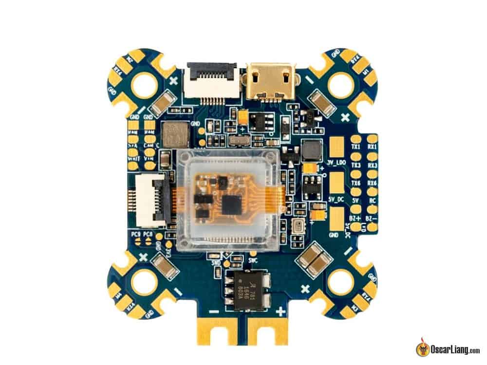
Soft Mounted Gyro
The Omnibus Fireworks V2 has a soft mounted gyro in a protective case, and the ribbon cable that connects the gyro is also reasonably protected. Because of that you no longer need to soft-mount the board, potentially saving you from spending more on rubber bobbins :)
The Gyro sensor is a ICM20608 which allows for 32K/32K sampling rate and looptime. There is a spare SPI connector, so you can plug in a different gyro such as the MPU6000 if you wish according to the manufacturer.
Hall Current Sensor
Instead of using the traditional shunt resistor to measure current, the Fireworks V2 uses a different approach. It uses a hall effect current sensor to detect current by measuring the magnetic field induction.
One benefit is that you no longer need to calibrate the current sensor! (at least that’s what the manufacturer promises). The current scale you need to enter in Betaflight is 175.
Shut resistors also have resistance which can cause a small amount of power loss. So it’s good to know we no longer need to worry about that on this board.
The default current sensor is rated for 150A, if you need a higher rating you can solder an additional resistor to the board to increase the limit to 320A. But seriously 150A is more than enough for us, because it’s pretty hard to find a battery than can put out that kind of current :)
8V for FPV Gear
It’s nice to see there is a dedicated 8V/1A power for FPV gear, and not just 5V. Most FPV components support direct LiPo input, but the lower input voltage means less heat, as well as additional power filtering.

Board Layout
The Omnibus Fireworks V2 is kind of an upgrade from the Omnibus Corner we have been featuring in our list of “Best Flight Controllers”, which share a similar style.
First of all, the solder pads appear to be nicely sized and easy to work with. They are separated into 2 groups by their functions, and duplicated on both sides of the board which is convenient.
There are solder tabs for the ESC extended around the mounting holes for standoffs. Not only this creates room for the FC it also makes soldering easier and wiring cleaner. Notice the small cutout is a nice touch to the design so you can fit the power wires inside the cutout and nothing will be sticking out on the top of bottom.
At each corner, there are ESC ground and ESC telemetry pads alongside every ESC signal pads. There are solder pads at each corner for you to “surface mount” extra SMD tantalum capacitors if you use some really noisy components, and don’t want to have electrolytic capacitors hanging off the board.

4in1 ESC Support?
It has a ribbon cable connector for 4in1 ESC’s. But as far as I know there isn’t many 4in1 ESC’s that use ribbon cables, apart from their own Typhoon32 4in1 ESC.
Where to Buy?
- Banggood – http://bit.ly/2MyLnE1
- Amazon – https://amzn.to/2MxsUYG
13 comments
Do you happen to have the pinout for the gyro socket? thanks
are the serial ports 5 V tolerant ?
This i2c is not working
Which cable should I buy to connect a 4in1 ESC? I need please the exact name or type.
It’s incredible that there’s nothing on their website
4in1 ESC should usually come with the cable. But make sure you check the wire order, sometimes it’s reversed.
So, SBUS is listed as UART 1, but the tab labeled for smartport is also labeled tx1, and the SBUS tab is it’s own tab separate from rx1. So, this seems to imply SBUS is on rx1 and smartport on tx1, but I thought this was not a thing you can do. Am I wrong?
the pic you have at the top of this article is a different FC than the one in the pics throughout the rest of your article. Not sure which is which.. I am trying to setup a kamikaze f4x advanced FC, which looks identical to the one in the top of this article. I’m assuming that underground FPV simply branded their own version of the fireworks FC. I actually tried flashing the omnibusfw target to my FC but it doesn’t work. the gyro isn’t responding, so there must be something different. anyhow, I’m having orientation/motor mapping issues with my f4x FC, which is how I found your article. just thought I’d let you know about the picture conflict in your article. which is which? thanks.
They are just different revisions, Airbot is known to release a new version of the same FC every 2 weeks lol
The USB Connector is on the opposite side of the Power Input – that’s strange.
Many Quads require the power input pointing to the tail, so USB will be pointing forward, and not accessible.
No, i think you looked at the picture wrong. The battery connections will be on the left side between 3 and 4 motors and the usb on the right side between 1 and 2 motors. I dont care for that layout but for me its not a deal breaker.
Where can you connect your servo’s on this board?
I assume you would connect the battery directly to this, so no need for a PDB?
Yes you can connect LiPo directly, it’s an AIO board which has PDB integrated.