Resource Remapping is an awesome feature in Betaflight, it allows you to swap pins around on a flight controller. Resource Remapping is powerful, you can change motor order, relocate pins in case of ripped-off solder pads, and so on.

Further Reading: More Tutorials on Betaflight Features.
Why you might need Resource Remapping?
- Not enough UART TX/RX
- Ripped solder pads
- Requires more motor output for hexacopter configuration
- Missing PPM receiver input
- Missing programmable LED output
- Servo output
- Change motor output order
How does Resource Remapping work in Betaflight
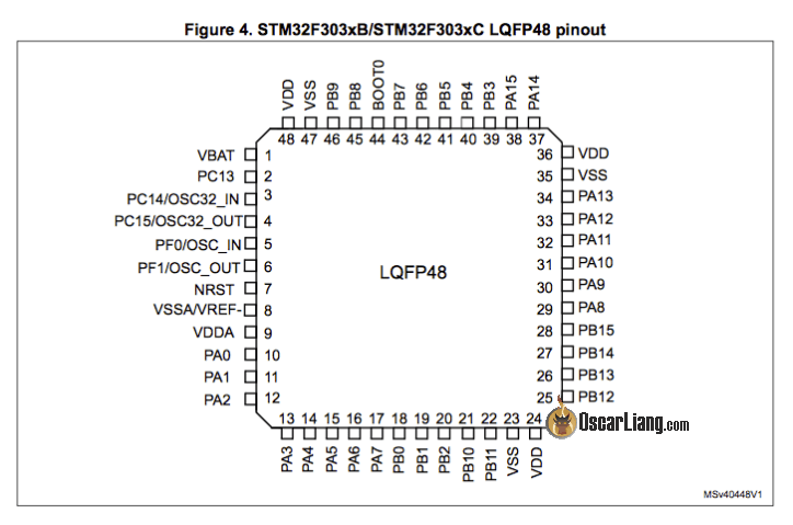
There are many pins on a processor (as shown in the top image), and each pin might be assigned a specific function by Betaflight. Resource Remapping basically allows we to re-assign those pins with a different function.
This feature is available in Betaflight V3.1 or newer versions.
In Betaflight configurator CLI, type “resource”, it will return the available functions that we can change, and their current pin assignment:
# resource
resource BEEPER 1 C15
resource MOTOR 1 B07
resource MOTOR 2 B06
resource MOTOR 3 B05
resource MOTOR 4 B04
resource PPM 1 B03
resource PWM 1 B00
resource PWM 2 B01
resource SONAR_TRIGGER 1 B00
resource SONAR_ECHO 1 B01
resource SERIAL_TX 1 A09
resource SERIAL_TX 2 A14
resource SERIAL_TX 3 B10
resource SERIAL_TX 11 B01
resource SERIAL_RX 1 A10
resource SERIAL_RX 2 A15
resource SERIAL_RX 3 B11
resource SERIAL_RX 11 B00
resource LED_STRIP 1 A08
The format is as follow:
resource [Function] [Index] [Port]
To change a pin for a function, you just follow the same format, and enter save at the end.
In the following we will show you some of the common usage of Betaflight Resource Mapping.
One very important note about this is, some of the pins of the processor might be unused, and does not connect to any solder points on the flight controller. The port you are changing the function to should ideally be a breakout pin on the flight controller (somewhere you can solder to easily). Otherwise you might have to solder a wire directly to the extremely tiny “leg” on the processor, which is really hard to do.
Some notes:
You can remap motor outputs freely, but if you want to add a motor output using other pins, you might run into “DMA conflict” if you use DShot. LED_Strip is your best bet for that.
You can’t remap hardware serial, but you can use hardware serial pins for other functions.
LED_STRIP pad is Powerful!
You can guarantee to use the LED_STRIP pin for almost anything, such as motor output, soft serial etc, that’s because it usually has its own timer and DMA channel.
Make sure it’s LED_STRIP that you want, and not LED! These are two different resources. (LED is the tiny status indicator that blinks when you power up the FC)
Camera Control is Strictly Camera Control
Because FPV camera control requires resistors and capacitors to work properly, they are normally already built into the flight controller, connected to the “camera control” pin. Because of this, you can’t use it for anything else. Depending on the capacitor value, you might be able to use it for slow speed protocol such as SmartAudio, but usually not any high speed protocol.
ADC Resources
These are all “ADC” resources – analogue to digital converters.
- ADC_Batt – battery voltage input
- ADC_Curr – current sensor input
- RSSI – RSSI input
You can remap these 3 resources to each other, but you can’t remap these to anything else.
How to change LED Strip Pin?
For example if you want to change LED strip to A09, simply type in CLI:
resource LED_STRIP 1 A09
save
Note that it’s LED_STRIP! There is another resource called LED, which is the status LED on the flight controller. If you remap LED instead of LED_STRIP, you won’t get what you want, but instead turns off the status LED on the FC.
How to change motor order/output on flight controller
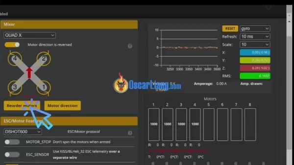
Update (Oct 2022): you can now change motor order inside Betaflight configurator and avoid messing with resource commands in CLI. Here’s an animated how it can be done.
If you want you can still use the old method as described below.
If you have a quad with motors in the wrong order, you can either undo the soldering and swap the motor outputs on the flight controller, or simply fix it in the software using Resource Remapping!
First thing you want to do, is to find out the current motor order. You can do so with the Motor tab in Betaflight.

Remove all propellers!
Use the motor tab to spin up the motors one by one, from motor #1 to #4 and write down the order on a piece of paper. For example, we have:

Now type “resource” in CLI, and find the 4 lines specifying the pin assignment for the four motors:
resource MOTOR 1 B07
resource MOTOR 2 B06
resource MOTOR 3 B05
resource MOTOR 4 B04
Please make a copy of these lines in a text file, if you make a mistake you can just go back.
Now you can write down the pin numbers next to the motors:

On the same paper, replace the motor numbering with the correct ones:
- rear right motor should be #1
- front right motor should be #2
- rear left motor should be #3
- front left motor should be #4
It should now become clear what motor numbers you have to assign to the pins.

In our example,
- B06 should be “motor #1”
- B04 should be “motor #2”
- B07 should be “motor #3”
- B05 should be “motor #4”
To change the motor pin assignment, type these lines in CLI:
resource MOTOR 1 B06
resource MOTOR 2 B04
resource MOTOR 3 B07
resource MOTOR 4 B05
save
And that’s it!
Update (Feb 2022): since Betaflight 4.3, you can now remap motor order using the Configurator’s graphical user interface. No need to use the complicated CLI for that anymore.

How to change buzzer (beeper) pin
It’s just as simple as the examples above… BUT!
You cannot just assign any pin for the buzzer, you need to do more!
That’s because the buzzer can draw a fairly large amount of current (more than the STM32 processor can handle), therefore there is usually a transistor in place. The transistor handles the current for the processor, and it’s controlled by a signal from the processor. If you connect the beeper directly to the STM32 processor you could potentially fry it.
It’s probably not a good idea moving buzzer pin around considering how much work this is. But if you do decide to move the buzzer to another pin, you will need to build an external power circuit like this. This is an example for the CC3D FC’s, for the most reliable choice of component and circuit please consult your own FC manufacturer.
![]()
Multiple functions sharing the same pin?
Sometimes a pin can be shared by multiple functions in Betaflight, if this is not your intent it’s best to free up the pin from tasks that are not required.
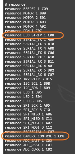
To check, simply enter “resource” in CLI. In this example, you can see that pin C08 is shared by two functions: LED_STRIP and CAMERA_CONTROL.
Further Reading: How to setup Camera Control in Betaflight?
If we are not using LED Strip, but camera control, you can free up pin C08 from LED_STRIP by typing this command in CLI:
resource LED_STRIP 1 none
That’s it! :)
Not Enough Serial Port?
If you run out of hardware serial port (aka UART), you can turn spare pins as software serial port, aka Soft Serial.
For example, you can use LED_STRIP, PPM, spare motor outputs.
What Pads That Cannot Be Remapped?
Voltage (5V and battery voltage) and ground pads cannot be remapped as these are physical connections that doesn’t go through the processor.
Camera input and output (for Betaflight OSD) also cannot be remapped as these go through the OSD chip, and not the main processor.
Edit History
- Oct 2017 – tutorial created
- Feb 2022 – updated for Betaflight 4.3 new feature
74 comments
Hello oscar.
I’m using the Rotor Riot Brave F7 flight controller. There are no dedicated led pads. I’m trying to decipher the process of running addressable rgb leds with this flight controller. Any help would be appreciated.
Thank you.
is it ok for self powered buzzers like vifly finder to use led strip pads without fry fc ?
Great value article!
DUDE! I spent over a year trying to get my PAVO 30 pusher quad working, the pusher orientation was messing with the config so it kept autoflipping. Now it works! And now I just need to find my battery charger, lol!
THANK YOU!
Hi Oscar
I accidentally knocked off my buzzer transistor from my fc and that pad won’t work.the transistor pins are too small for soldering. I have a vifly finder v2, I wired the +5v and gnd , and I changed the resources map to use a uart.when the switch for the buzzer is on in my controller it buzzes nicely in usual intervals, however when I flip buzzer switch off, the buzzer remains ON continuously and the uart tx or rx are ground(-ve).I measured the current passing through the yellow buzzer-ve to be 0.035mW.so the buzzer now works but it’s also constantly on when I don’t need it.i don’t have led_strip in my resources list..it’s a skystars mini HD 3 Pro, the manufacturer has led_strip in wiring diagram but not listed in resources, pls guide me.thanks in advance
Somebody correct me if I’m wrong but it sounds like I’m able to change the function of a buzzer pad? I want to swap one to be an LED strip
Hi Oscar,
I just discovered this article, actually someone referenced it to me, and its great!!
I have lifted a TX2 pad, hence being referenced here, and after reading I’m going to use an available Led-Strip pad to assume the role of TX2. Actually is the same example you give above.
However I also read, and others have commented, about the softserial port, and now I’m confused. By doing the command “resource LED_STRIP 1 A09 save” is the LED_STRIP now effectively a UART TX pad, or is it a softserial, and it need to be configured for such?
For context, I’m using this UART to connect a EP2 rx.
tks
First of all, you can’t use soft serial for receiver because it’s too slow. The only exception is Frsky Smartport because it’s only a telemetry connection so speed isn’t a concern.
Secondly you can’t remap another pad for use of hardware serial, you can only use the UART that come with the flight controller. You can only remap LED_Strip to soft serial, but as mentioned it won’t work for your receiver.
Maybe you can find out where the lifted pad is connected to in the microprocessor, and try to solder the receiver to the leg of the processor.
Thanks for the reply Oscar. That being the case then, I will actually remove the RX from the VTX and map a softserial for it, and use RX1/TX1 for the receiver. Does that sound right to you?
Yea that sounds good to me!
Thank you!
Hi Oscar! Quick question for you: I want to add a servo to control a small light on my quad copter. I’m using the Speedy Bee F7 V3. From the article above, it seems like I would have to use the LED pin on the flight controller. You also mentioned sharing a pin. How does that work? I want LEDs to be working on my quad copter, but I also want to be able to control the servo. So if I have two things map to the LED pad, wouldn’t there be a conflict? By the way, thanks for all the great content, I love your website! I’ve learned so much over the last couple of years.
No, you can share the same UART (which has tow pins TX and RX) for two different tasks by remapping one of them for softserial, but you can’t share the same pin for two different tasks.
ESCSERIAL1 is the current pad on fc?
Can i remap that for softserial?
where do you see ESCSERIAL1? Which FC?
Regarding moving the buzzer/beeper. One likely reason to do this (which is what brought me here, anyway) is if you lifted a pad.
One note to add to the above is – based on what I’ve read elsewhere, and consistent with the diagram above – is that if you have lifted the +ve pad but not the -ve one then you could leave the -ve as is and move the +ve to another 5V source. (See https://www.reddit.com/r/Multicopter/comments/p8hkwx/solder_pad_for_buzzer_ripped_off_can_i_fix_this/ )
Hi Oscar
I have ripped the Smart Audio pad on Flywoo 13a AIO can it be resourced to led pad or any other pad Kindly guide
Regards
Can resource remap resolve a situation where LED_STRIP doesn’t work? Can remapping to another pin resolve the problem?
I have a question about using the camera control pin for smart audio, you said it depends on the capacitor value. I have a flight controller and it’s capacitor on camera control is 1uF and the resistor is 470 ohms. Is that low enough to use with smart audio? The flight controller is the SPracing H7rf. I want to use camera control for smart audio to keep all of the wires for a vtx on one connector. Here’s a link to the manual for the flight controller
seriouslypro.com/files/SPRacingH7RF-Manual-latest.pdf
Thanks for all the amazing guides you post!
Hi, I recently remapped the motors on my whoop flight controller because I had to flip it so the usb is facing down. I’ve done this before no problem, but this time, after remapping the motors, I tried to reconnect to betaflight and now the fc will not connect. It just has a solid red light when connecting via usb or powerd by battery, Also, when powering up with a battery, it only does the first half of the normal chime. Any idea on how to resolve this?
Hallo
Can I remap signal pad to another place?
Because my pad already broken.
And how to remap.
Thanks for answer
I have same issue… did you figure it out?
When you finish remaping. How to save it?
type save and press enter
5v pads and ground pads can indeed be mapped. A hi logic line is at 5v. A low logic line lives at 0v and is therefore a ground. But you’ve already pointed out the limitation in this approach – it’s exactly the same as the beeper situation. These pins can’t source or sink significant currents, which is why you have to introduce the transistor.
Hi! I’m interested to add a pinio to a 10v pad (to use like a pit mode for my O3 Naked version, do you know if it is possible?could you help me?)
Hi, I have omnibus F3, I want to make hexcopter, do I need to remap pin, or just connect extra two esc/motor to pwm #1 and #2 ?
Thanks
I have the happy model crazy BF4FR Is lite brushless FC and need to change the 3 pads on the motor output to somewhere else could anybody point me in the right direction and if it’s even possible? to what pads I could change them to I’m a newbie and this is driving me crazy….please lol…ty
Hi I have a F405 Brushless Flight Controller from a betafpv 75x 2s and iv damaged the pins connecting the frsky xm+ receiver.
And im not really sure what alternative pad to use for sbus/ppm
You can connect SBUS to one of the RX pins (the RX pin of any UART), but you have to make sure you get the “uninverted SBUS signal” from your receiver, because F4 FC doesn’t have built-in inverters you can find it following this guide.
I saw your response to another user trying to remap a motor- usually this is due to a damaged pad or just involves rearranging motor order. I’m trying to use my Omnibus F4 v2 FC which is generally used for a quad for a hex build. Resources lists 6 motors defined, and I successfully remapped M5 to the Led strip. I just have to find one more available pin with the right timing. You mention this timing in one of your responses but not how to find one which is appropriate. I just tried using the FC status LED but that didn’t work. I’ve also tried using UART Tx/Rx pads. That didn’t (quite) work. M6 DOES respond but it is generaly twitchy and not correct like M5. Help?
Hi Oscar,
In my OMNIBUS F3 BTFL v3.1.0, by default all motor/servo output uses the pins, having timer functions. I’ve tried mapping servo output to a pin, let say new pin is pin 37 – PA14, that isn’t timer function PIN.
And It doesn’t work. Is It true, that servo pin must be a pin, having timer functions.
Thanks.
Andrew Do.
Hello. I have an FC from TYRO69 on STM32F411 I would like to connect a barometer to which processor pins should I connect?
Thank you for your answer.
This is a kind request for help.
I would like to put crossfire on my first quad, a M515 from Diatone. I connected the crsf Tx from the nano receiver to the pin marked with sbus on the flight controller (mamba405). So far I can see the control signals in Betaflight when I move the sticks. This tells me that the pin sbus is actually serial rx1. I think I should also connect the crsf Rx pin from the receiver to the serial tx1 but I do not have a pin for it. I do however have a pin marked with ppm. The question is what do I gain by connecting the second crosfire pin and if I can use the ppm pin. I cannot use serial3 because that is for smart audio and on serial 6 I have a gps doing it’s thing. I am just new with crsf.
HI, Question, is the Buzzer pad free to use? Can i use it to power a GPS or is this pad only for a buzzer?
thanks
Rob
Need your help. My Sbus solder pads are ruined on my omnibus f4 what can I do to connect sbus without the pads?
Hi Oscar , Can i remapping a led pad to a active buzzer ? Because my FC don’t have buzzer pad. My FC is matekf411 aio 12a betafpv.
This is tutorial post form japan show how to build and change a led strip to a buzzer :
burariweb.info/drone/toothpick/betafpv-hx100-self-made.html
Thanks for your reply.
Howzit Guys!
Recently build an 3 inch with a succex f4 v2, with vtx. accidently ripped the TX 1 pad for telemetry for my rxsr rx. Can i map tx 2 for the smartport? And how do i go about in doing it? Im a noob and assistance will be appreciated
Actually you might be able to assign even a motor to a different pin: In my case (Mamba F722 Mini, a really really unstable thing) di not power up motor 2. There is no extra motor pin on the Mamba.
the resource for motor 2 is C09. I want to map it to C07, as this is bound to UART 6 RX, which I do not need.
Then you need to unassign the original source, here:
resource SERIAL_RX 6 none
Then prepare C07:
timer C07 AF3
dma pin C07 0
Finally assign your motor:
resource MOTOR 2 C07.
SAVE.
Now solder the ESC connection to RX6 instead of M2.
For me this worked, all motors spin up.
do you assign this c07 same as c09 was before ?
“Then prepare C07:
timer C07 AF3
dma pin C07 0”
ok so I am using the Matek f405-STD and I burned out the S1 pad for motor 1 and want to switch to the LED pad. is that possible?
Motor 1 is:
RESOURCE MOTOR 1 C06
the LED 1 is:
RESOURCE LED 1 B09
shouldn’t i be able to switch them around by using command :
RESOURCE MOTOR 1 B09
SAVE
But that does not work. actually nothing will work at that point, the start up sound doesn’t go off normally as it should.
I have switched back the way it was and then motors 2-4 start to work again.
Then i read the post again and tried
RESOURCE MOTOR 1 NONE
RESOURCE LED 1 NONE
RESOURCE MOTOR 1 B09
RESOURCE LED 1 C06
Still it doesn’t want to work. What am I missing here?
you cannot just use any pin for motor output, it has to have the right timer. See if there is motor 5 output on the board, you can remap it to motor 1, otherwise you would have to check with Matek technical support and see which pad you can use.
Can a gyro be remapped on a kakutef7 . is the chip pinout available somewhere i have not be able to find it . ? ?thanks
Type in resource in CLI, those are all the pins/resource you can remap. You can’t remap a gyro, no.
Hi Oscar. I am using a Matek F411-WING to control a Strix Nano Goblin plank. I have enough UARTs to connect VTX control, but not Runcam camera control. Since VTX control and camera control are two separate functions in iNav OSD stick control, can I connect both to one UART and use stick commands for both? Thanks!
Oscar I’m newbie in regards to using CLI in BF, the resource command pad designations, are they generic from board to board or how does anyone know the designation of say the LED pad (designation meaning in form of A0# or B0#). Looking to remap for use of camera control on diatone f4 Mamba mini found that B09 (bp9) is resource to remap but how do people know this or know what B09 Is labelled as on board itself.
The board designer decides what pins to use for what functions. That’s why it’s unique from board to board.
I have the Betaflight F4 fc and a motor pad got ripped up from the fc . Its the signal wire from fc to esc. So we tried to resolder it to the little connection we saw . That has been unsuccessful. We were looking under the recource command and see there is a 5th motor free and available . We have been doin research and cant find out where the pins are locaated for the 5th motor. Can you help please.
Thanks
Is it possible to remap a motor to the buzzer? Had a 4in1 esc grenade and fry the #2 & #3 circuits. I remapped #3 to led and it works. So wondering if I can use buzzer for #2?
Am I understanding correctly that each X## pin value refers to a specific physical pad on the board? So in my case, on the Succex Micro, the “LED” pad could have a label of “A08” on the board? I base this on “resource LED_STRIP 1 A08”.
Cheers.
The pin number refers to a specific pin on the processor, not a pad on the flight controller.
But each pad might or might not connected to a specific pin on the processor.
Hi Oscar greetings from Italy. Can I reassign a pen pin to another? I have a problem with an Aitbot F7 v2 (motor 4 don’t arm). I make all the test (change esc and motor from 2 to 4, reflash beta and other but in blheli32 is not possible to recognize esc 4. I think that the pin for pwm4 is gone so I need another pin for that esc/motor. Thanks for the answer. Andrea
Hi i have an aikon f4, recently while applying solder to the pads the sbus pad (rx1) lift and gone.. i remap the serial rx1 to rx2 but din not get any connections try to connect to the other serial rx pads w/o remapping didn’t get any connections..
need help
i have the same board with the same issue .. what i did was i checked for schematic of the board .. the pin get its path from back of the board .. gently scratch the surface of board from exact location of sbus pin .. you see a hole that separated from sides .. isolate that by scratching deeper like 0.5mm around it .. then apply some solder .. then connect your wire .. hope this work for you .. if you want i can send you some pictures .. hit me in discord ..
EhsanRT#1123
I have a quick question. Im trying to set up soft serial on tx6 on my cicada aio fc so i can get smart port to work without having to do the r-xsr hack. When I check resources in the cli i see Pwm 3 and serial_TX 6 share that same resource. So my question is what is pwm 3 and do I need it? Or can I just free up that resource and go ahead making it a soft serial uart? Thank you for any help you can provide.
Hey man…I’ma big fan!
I have a Cyclpos HD camera that has an IO port for triggering the record with ground (don’t have to push a button). I would love to do it with a switch on the TX -> start record -> stop.
I tried the LED data output on the FC, it works but the recording stops after 5-10 seconds by itself.
I have several free UASTs free. Can one have multiple buzzer outs? I read that the Buzzer port is switching the ground so I could use this but I’m in need of the buzzer function (lost model…).
Any idea?
Peace and keep dooin ya thing!
Can I use this function to shift pwm input pins of 2IO to 1IO port on Spf3 ,just like we setup pwm on F1 fc
This is one of the things i really struggle with in BF . I just can’t seem to fully understand it i have tried reading many sites and i still can’t figure it out..What i need is more UARTS on my Omnibus F4 pro v2 i have used all them up hooking up GPS,MAG, 3DR telemetry radios running INAV..I have a Flysky x6b on the PPM pad but i really ant to use a Frsky r-xsr but can’t figure out how to hook it up cause all the uarts are full i think.. I need one for SBUS and one for S-Port
hi Oscar, big fan, keep up i realy enjoy each of your post.
On my dys f4 pro, i have motor 3 signal that is ripped…..where can i remapped it?
There are M5 and M6, you can remap M3 to one of these :)
I’m wanting to remap the motors on the Lumenier alpha f4s fc. When I went into resource, it shows 6 motors instead of 4. Do I use the first 4, or the last 4?
They are listed as follows: Motor 1b00
. 2 b01
. 3 a03
. 4 a02
. 5 a01
. 6 a08
I’m new to this and didn’t expect to see six motor numbers. Any help would be appreciated. Thanks.
Your FC probably have 6 motor outputs, but you are normally using the first 4 for quadcopters :)
Is it possible to remap a led strip pin or uart to become adc_curr (current monitoring pad)?
I have a Fortini F4 FC and want to hook up a speedy bee bluetooth. Can i sue the UART6 and RX3 pads for this?
hi Oscar it s Presko from France ??….
i have a problemon my Quad… what is name of the esc 5 on the FC in ressource list because i would like to change the pad signal of my esc 1 it was ripped …..so i want to use the signal pad 5 from the backside for my esc 1…
i hope i am understandable
thank you guy
it’s usually labelled as motor 5.
But not every FC has more than 4 motor outputs.
I think you can use the LED pad.
Hi Oscar,
I just had to remap my motors and had some issues following your guide. I checked on the RCgroups betaflight thread and was told I needed to unmap the motors first using the following commands
resource MOTOR 1 NONE
resource MOTOR 2 NONE
resource MOTOR 3 NONE
resource MOTOR 4 NONE
This solved my issue. I am running betaflight 3.3 on this board.
Thanks Stewart,
you saved my time…I had the same issue after a direct remap. I’ve changed the motors, the FC…and finally read your post :)
!!!
That is correct! Oscar’s explanation, although helpful, will not work with any BF version. You can’t assign two motors to the same header number, you have to disabled, then re-assign, as you have stated.
it works for me from BF3.2 all the way up to BF3.4
Helo Oscar, Sorry for this long description/question!
This resource mapping info was a great find. Thanks. I have a question and am a newbie also and having problems getting Ws2812B led strips working on my HGLRC XJB F428 (Omnibus F4 V2).
The LED strip will not light up at all with my new FC and it did light up and work with my old HGLRC XJB F425 FC (that does not work anymore!)
AM having BF 3.2.3 as from the factory on my quad on the connected F428 FC.
I have done some voltage testing using a multimeter on the FC F428 and these are the results.
1)I checked the resources mapping using the instructions from the Project Blue Falcon video and according to the board the Resource LED strip is on A01 and when I checked using a multimeter resource A01 which is actually pin 15 on the chip and kept the other probe on the labelled LED signal pad (as seen on the photo attached) there was a ‘beep’ so I assume the resource mapping is O.K.
2) I checked the 5V line voltage on/at the actual LED strip PAD after the 1N4001 diode connection and the voltage was 4.67 Volts at that LED strip pad. The 5V LED line PAD on the FC before the diode connection is measured at 5.337 Volts. So the diode for sure has dropped the LED power voltage to the LED strip.
3) The LED signal line voltage on the actual LED strip signal pad was measured at 1.403 volts. The LED signal line voltage on the LED signal PAD on the FC reads 2.059 Volts.
4) Just a question – I enabled the Pr-earm mode in beta flight does this have anything to do with the LED not coming on?
5) Just a question – I also before this enabled the LEDLOW mode in betafllight (I did not know what this was) and removed the mode also thereafter and is not active at all. Will this have something to do with the LEDs not working?
6) The loop Ghz in configuration tab on BF on mine is at default 2Ghz, is this O.K ? or can this cause the LED not to function?
7) When I connected the same LED strips to an ARDUINO board the same LEDs work and light up so the LEDs are working OK for sure also! and my LED settings on BF also gets saved!
Again sorry for all this information, I feel based on the above checks and voltage reading and mapping checks that all that is O.K and for some reason the LED settings are not getting saved due to something.
MY MAIN QUESTION
(a) Should I change the resource mapping. For example when I connected a 2 LED with Buzzer strip and enabled the buzzer the buzzer worked and sound came out but not the LED lights. So should I remap using your instructions the LED signal to the buzzer to see if this works?
(b) If I should not assign the LED to the buzzer what other pin could I assign safely. Below I have attached my current resource list fyi.
Any help or advise will be great as am waiting for HGLRC to open after Chinese New Year holidays next week also !
Thanks
# resources
Unknown command, try ‘help’
# resource
resource BEEPER 1 B04
resource MOTOR 1 B00
resource MOTOR 2 B01
resource MOTOR 3 A03
resource MOTOR 4 A02
resource MOTOR 5 A01
resource MOTOR 6 A08
resource PPM 1 B14
resource PWM 1 B14
resource PWM 2 B15
resource PWM 3 C06
resource PWM 4 C07
resource PWM 5 C08
resource PWM 6 C09
resource LED_STRIP 1 A01
resource SERIAL_TX 1 A09
resource SERIAL_TX 3 B10
resource SERIAL_TX 6 C06
resource SERIAL_RX 1 A10
resource SERIAL_RX 3 B11
resource SERIAL_RX 6 C07
resource INVERTER 1 C00
resource LED 1 B05
resource SPI_SCK 1 A05
resource SPI_SCK 3 C10
resource SPI_MISO 1 A06
resource SPI_MISO 3 C11
resource SPI_MOSI 1 A07
resource SPI_MOSI 3 C12
resource ESCSERIAL 1 B14
resource ADC_BATT 1 C02
resource ADC_RSSI 1 A00
resource ADC_CURR 1 C01
# resource list
Currently active IO resource assignments:
(reboot to update)
——————–
A00: ADC_RSSI
A01: LED_STRIP
A02: MOTOR 4
A03: MOTOR 3
A04: MPU_CS
A05: SPI_SCK 1
A06: SPI_MISO 1
A07: SPI_MOSI 1
A08: FREE
A09: FREE
A10: SERIAL_RX 1
A11: USB
A12: USB
A15: OSD_CS
B00: MOTOR 1
B01: MOTOR 2
B03: FLASH_CS
B04: BEEPER
B05: LED 1
B06: FREE
B07: FREE
B08: FREE
B09: FREE
B10: FREE
B11: FREE
B12: FREE
B13: FREE
B14: FREE
B15: FREE
C00: INVERTER 1
C01: ADC_CURR
C02: ADC_BATT
C03: FREE
C04: MPU_EXTI
C05: FREE
C06: FREE
C07: FREE
C08: FREE
C09: FREE
C10: SPI_SCK 3
C11: SPI_MISO 3
C12: SPI_MOSI 3
D02: FREE
Currently active DMA:
——————–
DMA1 Stream 0: FREE
DMA1 Stream 1: FREE
DMA1 Stream 2: FREE
DMA1 Stream 3: FREE
DMA1 Stream 4: LED_STRIP
DMA1 Stream 5: FREE
DMA1 Stream 6: FREE
DMA1 Stream 7: FREE
DMA2 Stream 0: FREE
DMA2 Stream 1: FREE
DMA2 Stream 2: FREE
DMA2 Stream 3: FREE
DMA2 Stream 4: ADC
DMA2 Stream 5: FREE
DMA2 Stream 6: FREE
DMA2 Stream 7: FREE
Use: ‘resource’ to see how to change resources.
Can I remap the video out pin? I ripped that port on my Racerstar F4S. Can I use any other pin for this? How can I do that?
No you cannot as video out and video in are not connected to the FC MCU, but the Max7345 chip for overlaying OSD in your video.
Nice! This resource mapping thing also comes in handy on some flight controllers where dshot is not supported on all motor outputs. (I still don’t fully understand why that is).
For example, on the PicoBLX flight controller. One of the motor outputs does not support dshot. But when we remap that motor to the pin where PPM would be connected to (and solder the signal wire of that motor to the PPM pin) then dshot can be used on all 4 motors!