
In this tutorial, I’ll share how I use Blackbox logs to tune filters and PID on a Betaflight FPV Drone. I will be using PIDToolBox as the primary tool for filter and PID tuning, with Blackbox Explorer as a secondary tool for Feedforward and general troubleshooting.


Disclaimer: This guide is meant for informational purposes only. The author holds no responsibility for damages resulting from actions taken by the readers.
Blackbox is not a must for tuning as explained in this guide, but it provides full insight into what’s happening with the drone and allows you to unleash its full potential. Things like noise filtering and tiny overshoots are visible only in Blackbox. If you’re a perfectionist or just someone who likes to tinker, this is the tutorial for you.
If you are new to Blackbox, make sure to check out the Blackbox for beginners tutorial..
I spent over 200 hours making this 8000-word tutorial! If you find my content useful, please consider supporting my work.
Table of Contents
Getting Started
Tuning goals
Using Blackbox to tune our FPV drone, we aim to achieve two main goals:
- More Effective Use of Filters: Use minimal filtering to minimize delay but enough to keep noise at an acceptable level.
- Optimized PID Gains and Related Settings: Ensure the drone flies precisely and responsively.
Basic configurations
0. Hardware Checklist
- Flight Controller (FC) Stack: Choose an FC stack with rubber grommets (gummies) for durability and noise performance.
- Metal Screws: Use metal screws for the FC stack; avoid nylon/plastic screws/standoffs as they are prone to breakage and vibrations. If spacers are needed, use soft silicone ones. Lighter titanium screws can save a few grams.
- Locking Stack Screws: Secure the stack screws firmly with a metal nut before mounting the 4in1 ESC. If your frame has pressed insert nuts, additional nuts are not needed. Tighten screws by hand first, then give a final squeeze with a wrench/screwdriver.
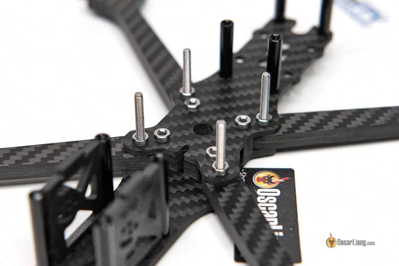
Use 4 plastic nuts to secure the FC stack. Tighten the nuts by hand only to avoid excessively crushing the gummies, allowing the soft mount to work effectively.

1. Blackbox Recording Settings
Select the following settings in the Blackbox Configuration:
- Logging Device: Onboard Flash or SD Card
- Logging Rate: 2KHz (or 1.6KHz for BMI270 Gyro)
- Debug Mode: GYRO_SCALED (records unfiltered gyro signal)
- Data Included: To save space for longer recordings, deselect unnecessary data like Altitude, GPS, and Magnetometer, or leave at default.

2. Disable the ADC filter in your OpenTX/EdgeTX radio (System -> Hardware) to reduce latency.

3. ESC settings:
I have a post explaining the best BLHeli32 settings. Here’s the summary (for 5″ drones):
For BLHeli_32 ESC:
- Rampup Power: 30%
- Motor Timing: 24
- PWM Frequency: Set LOW and HIGH to fixed 24KHz or 48KHz. 48KHz is generally safer for gyro noise, making your quad smoother and easier to tune. 24KHz offers better braking power, which is beneficial for prop wash handling and responsiveness, but with a higher risk of vibration. If you are on the fence, just go with 48KHz.
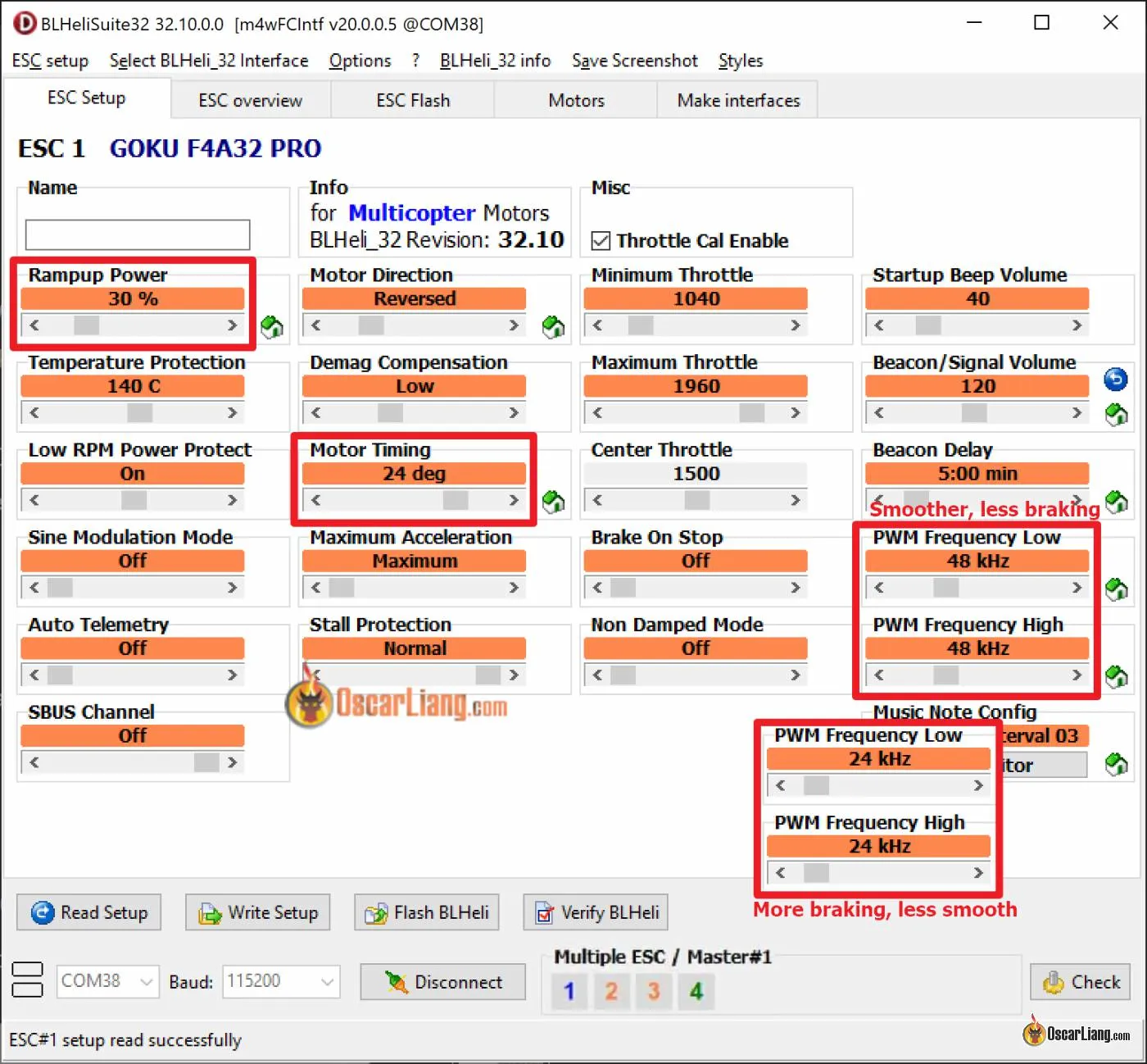
For BLHeli_S ESC, flash Bluejay to enable bi-directional DShot, required for RPM filter and Dynamic Idle. I have a guide on how to flash it here: https://oscarliang.com/bluejay-blheli-s/

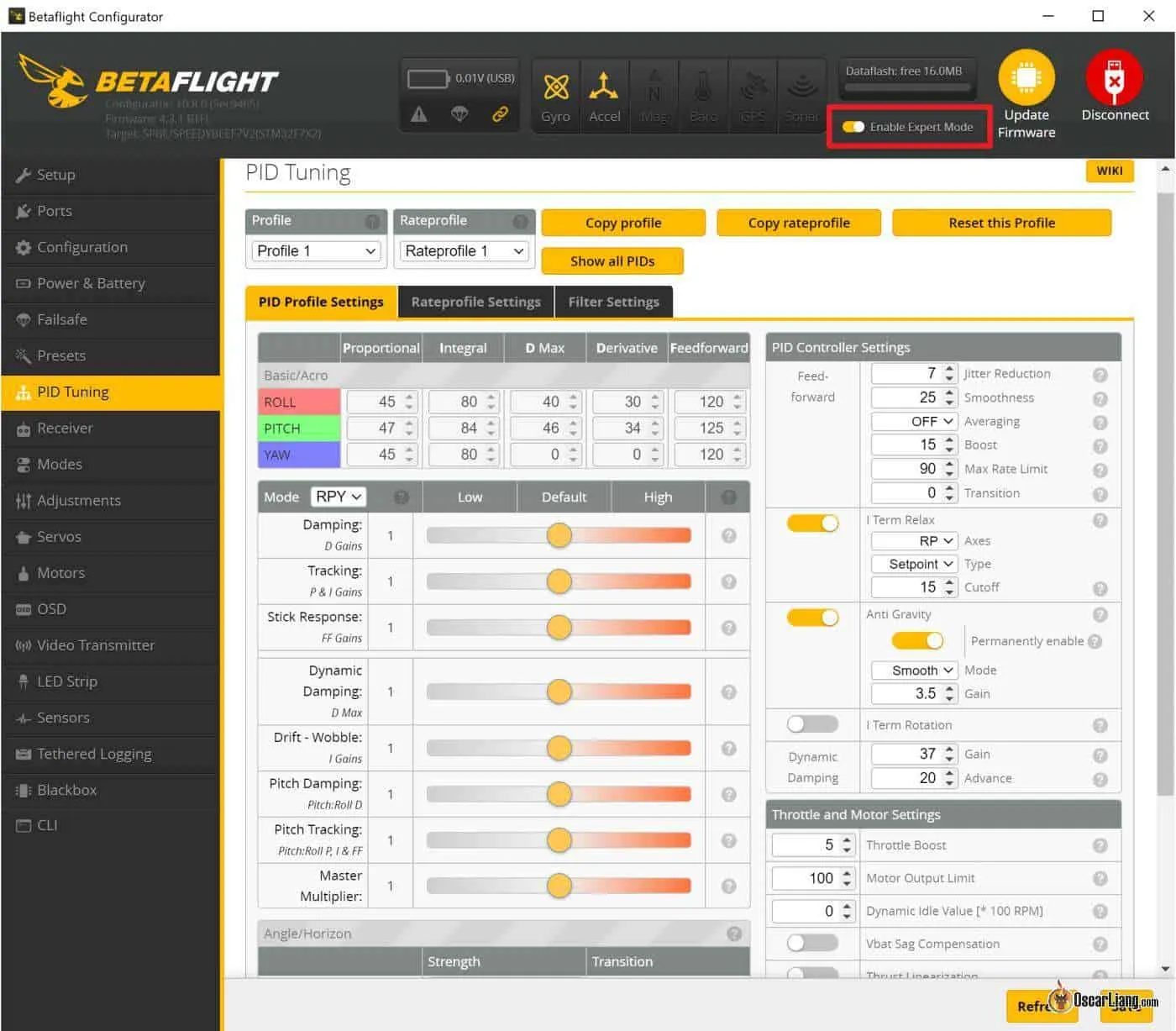
3. Flash the latest version of Betaflight firmware to your flight controller and leave PID/filter settings at default. Enable Expert Mode in Betaflight Configurator to access all sliders and options on the PID Tuning page.
In the Configuration tab, set your PID Loop Frequency, and in the Motor tab, set your ESC protocol:
- DShot300 for 4KHz or 3.2KHz Loop Frequency
- DShot600 for 8KHz Loop Frequency
4. In the Motors tab, enable Bi-directional DShot.
Most modern ESCs support Bi-directional DShot. I have a tutorial on how to enable RPM filter. For BLHeli_32 ESC it works out of the box, but if you have BLHeli_S ESC, you need to flash Bluejay firmware (tutorial) first.
Check if it’s working properly by running the motors in the Motors tab (without propellers) and ensuring the error rate (E) remains at 0%. If not, try a slower DShot protocol like DShot300 or DShot150. If errors persist, you might just have to give up on Bi-directional DShot and RPM filter.
Once enabled, go to PID tuning tab, Filter Settings, where you can enable the Gyro RPM filter, one of the best filters in Betaflight.

5. Load the appropriate RC_Link preset.

Different RC links require specific RC smoothing and feedforward configurations. Wrong config can cause stuttering and vibrations. My favorite RC link is ExpressLRS, check out what radio gear I use here.
Loading the suitable RC_Link preset in Betaflight will apply the necessary configurations automatically. Remember to choose options based on your flying style, for most people it would be Freestyle.
For Crossfire, lock the packet rate to either 50Hz (longer range, higher latency) or 150Hz (lower latency, less range) using the TBS Agent Lite LUA script.
6. Lower TPA
In the PID tuning tab, set the TPA breakpoint from 1350 to 1750 to avoid TPA masking oscillation issues at low/mid throttle during tuning. Fine-tune TPA at the end if oscillation issues occur at high throttle, but generally I would minimize the use of TPA whenever possible.

How to use PIDToolBox and Blackbox Explorer?
I will be using both PIDToolBox (PTB) and Blackbox Explorer (BE) in my PID and filter tuning.
- I already talked about how to use BE here: “the basics of how to use Blackbox in Betaflight“
- Download and install PTB here: https://github.com/bw1129/PIDtoolbox/releases/latest/
- This page explains how to use PTB: https://github.com/bw1129/PIDtoolbox/wiki/PIDtoolbox-user-guide
PIDToolBox will be our main tool, it’s by far the most powerful Blackbox tool available. It allows you to compare multiple logs side by side, making it easier to see the effects of your filter changes. The Step Response tool is especially useful for tuning PID. The spectral analyzer in PTB uses decibels on the Y-axis, providing more accurate and objective comparisons. PTB also estimates filter delays, which is very helpful.
However, PTB can be slower and less intuitive to use compared to Blackbox Explorer. For quick checks or troubleshooting a single log, BE is faster and easier. But for noise and filter tuning, PTB is the way to go.
Filters Tuning
You can find all the filters in Betaflight in the PID Tuning tab. Don’t be intimidated by all the settings, in this tutorial, we will mostly only focus on the green sections (RPM filter and Dynamic Notch) and adjust the orange sections (Gyro and D Term Lowpass Filters) using the sliders. No need to touch the red sections.
Further reading: Learn about the different types of filter in Betaflight in this tutorial.

Good hardware can reduce the need for extensive filtering. Ensure your frame is well-designed without resonance issues, use well-balanced propellers, and high-quality motors with smooth bearings.
Performing Flight for Noise Analysis
- Take Off: Fly forward with minimal throttle and stick inputs.
- Throttle Sweeps: Slowly ramp up throttle to 100% over 5-10 seconds. This test shows vibrations across the throttle range and frame resonances.
- Repeat: Perform 2-3 throttle sweeps, then land and disarm.
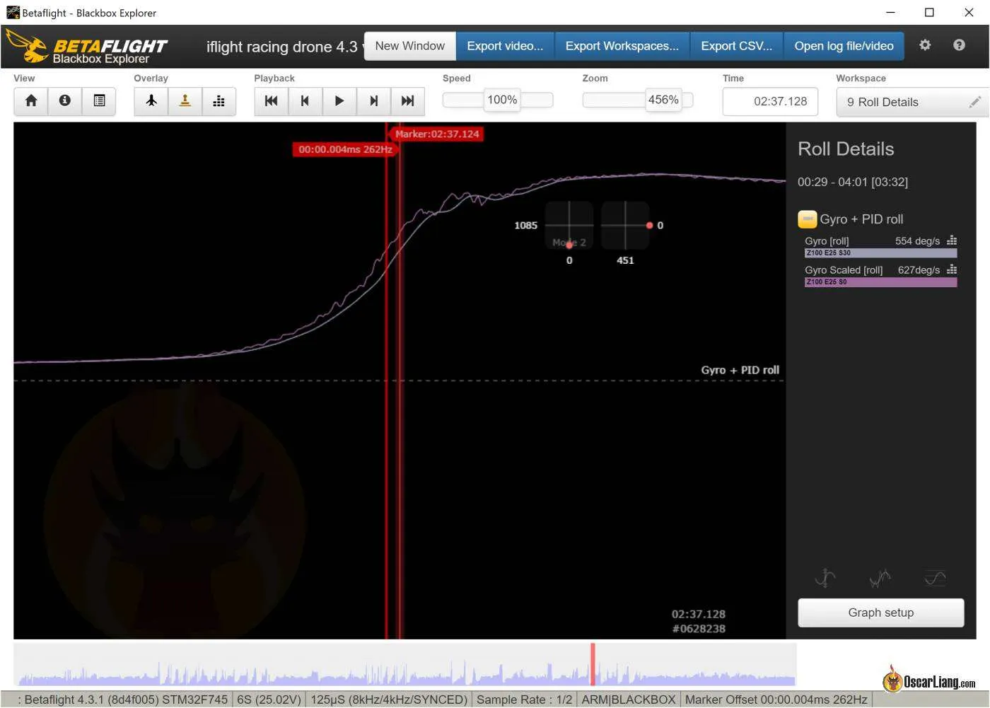
This is what a typical throttle sweep log would look like (see the bottom bar for throttle changes).

Gyro Noise Frequency Explained
Open the throttle sweeps log in Blackbox Explorer and click on “Gyro_Scaled” on the right hand pane, this is the unfiltered gyro signal. Remove the takeoff and landing parts of the log by pressing “i” and “o”.
Here’s a breakdown of the raw gyro signal frequency graph from a typical 5″ FPV Drone:
- Under 20Hz: Drone flight movements.
- 20Hz – 100Hz: Propwash and oscillations from suboptimal PID, problematic ESC config, bad RC link settings, etc.
- 100Hz – 250Hz: Frame resonance or loose parts.
- Above 250Hz: Noise from motors and propellers, and harmonics.

Everything below 20Hz is “good” drone motion reacting to the sticks.
Between 20Hz and 100Hz is where undesired vibrations, such as oscillations and propwash, occur. As a general rule of thumb, you want to see little activity in this frequency range. Having some is normal, but too much means you have an oscillation issue that needs to be addressed. Generally, we try to avoid filtering below 100Hz because those are real motions of the drone that we either want to work with or against. Filtering in this low-frequency range can actually make things worse because it introduces a tremendous amount of latency. Analyzing the spectra under 100Hz can give you insight into vibration or mid-throttle oscillation issues and how well the copter handles propwash.
We don’t care about anything above 1000Hz as these have little effect on our drone. What we want to focus on filtering is the noise between 100Hz and 1000Hz.
Delay Caused by Filtering
Perhaps not intuitive, but over-filtering can actually cause oscillation to show up as noise in the sub-100Hz spectra. That’s because filtering creates delay. When the quad tries to correct the error, the response might be too late due to the delay, which can be counterproductive. It can make the error worse and create a feedback loop, causing the drone to oscillate.
That’s why, if we use less filtering, noise issues under 100Hz can sometimes actually get better because latency is reduced and the quad can react faster to correct PID errors. Using less filtering also allows you to push PID gains higher, which makes your quad track setpoint better and helps combat propwash.
You can find out how much delay is added to the Gyro signal due to filtering by plotting Gyro and Gyro_Scaled and measuring the gap between them.
In PTB, it automatically estimates the delay caused by gyro filtering and D-term filtering (see the top right corner of the first graph in the second column).

Filter Strategy
My general filter strategy is to eliminate motor noise bands using RPM filter, then crush out frame resonances with dynamic notch filters, and finally, reduce the ambient noise floor with Gyro and D-term lowpass filters. I will be tuning filters in this order:
RPM Filter > Dynamic Notch Filter > Gyro Lowpass > D-term Lowpass
We want to use as little filtering as possible to minimize latency, but at the same time, we need enough filtering to avoid burning our motors when flying home with a bent prop. You can certainly play it safe and apply more filtering than needed, but over-filtering makes the drone feel disconnected and slow to react due to the increased delay. It can also worsen propwash. So, we need to strive for a balance.
Apart from checking Blackbox logs, motor temperature is another useful indicator in filter tuning. When motors get too hot, it usually indicates that the filtering is too aggressive.
Pro Tip: Hot Motors – How Hot is Too Hot?
As a general rule of thumb, if you pinch the motor bell and can’t keep your fingers on it for more than a few seconds, it’s too hot and you are probably pushing your settings too aggressively.
How Clean is Your Build?
Before we begin tuning, it’s important to check if you have a clean build. Start by performing throttle sweeps as previously described.
Load the log in PIDToolBox, click on the Spectral Analyzer, select “Gyro prefilt” (the raw, unfiltered gyro signal; “Gyro” is the filtered signal), and hit Run.

The default filter settings in Betaflight are fairly conservative, and most builds should be able to reduce filtering from there. If your quad is already noisy with default filter settings, instead of increasing filtering, you should look for possible mechanical or electrical issues. Ensure you have a capacitor at the ESC input power, all screws are tightened, and you’re using fresh new props, etc.
On a clean 5″ quad, there should be little activity between ~50Hz (the quad’s movements) and ~200Hz (motor vibration). If you have a lot of noise in this region, it could be electrical noise (perhaps the gyro input power is too noisy, or it requires an extra capacitor at the ESC input power) or mechanical (e.g., a wire hitting the gyro). Achieving optimal filtering in this condition would be more challenging.
As suggested by the author of PIDToolBox, it’s ideal to have the overall noise floor below -30dB above 50Hz. For D-term, it’s ideal to have the overall noise floor below -10dB. Examining the noise levels in these regions can give you a good indication of how smooth your quad flies. The noise level is influenced by the build quality of the drone, the quality of the hardware, and sometimes you might just have a noisy gyro.
If your quad is noisier than this (e.g., there’s a peak in the middle above 0dB), then you will need more filtering. It’s not the end of the world; it just means the latency will be higher, and you won’t be able to push PID gains as high.
Tuning RPM filter
Motor noise is the primary source of noise for FPV drones, and the RPM filter is one of the most effective filters in Betaflight for tackling motor noise. On a clean build, the RPM filter and Dynamic Notch filters will do most of the work, allowing us to disable many other filters to minimize latency.
Let’s look at some examples of motor noise:
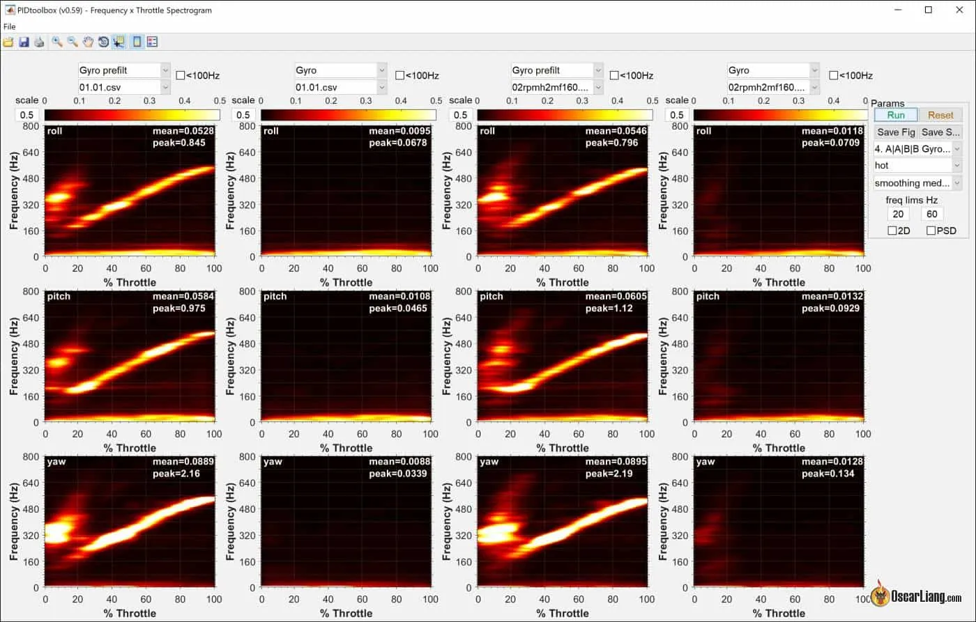
- Load the “Throttle Sweeps” log in PTB, click Spectral Analyzer and click “Freq x Throttle“.
- Under “Presets” select “Gyro Prefilt, Gyro, Dterm Prefilt, Dterm” and hit Run. This is what I call “heat maps”.

Here’s a breakdown of what we’re looking at:
- Close to 0Hz: The very bright horizontal line at the bottom (1) represents the drone’s motion reacting to the sticks.
- Around 200Hz: This horizontal line (2) indicates frame resonance. Its frequency doesn’t change with throttle position but is strongest where it intersects with the motor band.
- Fundamental Motor Noise Band: This diagonal line (3) is usually the brightest. Motor noise typically increases in frequency with throttle level.
- Harmonics: These are multiples of the fundamental motor noise band. In our example, harmonics (often dimmer and harder to spot) show up as lines (4) and (5). Try adjusting the scale if they aren’t visible. Note that 2-blade propellers tend to show more and stronger harmonics than 3-blade props.

We will use RPM filter to take care of these motor noise bands.
The goal is to optimize the number of RPM harmonics used and set the highest possible “Min Frequency” based on the starting frequency of the motor band. Fewer RPM harmonics and a higher min frequency result in less filtering and lower latency.
Use the Data Cursor Tool, click on where the motor band starts to find the exact frequency. Confirm this in the roll/pitch/yaw graphs and take the lowest frequency.

Here’s an example from my new Source One V5 build:
- On the left, is the default RPM Filter, 3 harmonics with a min frequency of 100Hz.
- On the right, I changed it to 2 Harmonics with min frequency of 160Hz
By reducing one harmonics and raise the cutoff frequency, you can perhaps see more unfiltered noise from the 3rd motor harmonics.
Although it’s pretty weak, it can still get amplified when it gets into D term. Let’s check the Dterm heat map below on the right, as you can see, a tiny bit of gyro noise has become pretty bad Dterm noise.

In this example, it’s probably better to have 3 harmonics in RPM filter.
The other thing you might have noticed is some noise around 116Hz left unfiltered because we raised the min freq to 160Hz. To address that, we have to lower Min Freq, i.e. around 20Hz below the noise frequency would be ideal.

Here’s a comparison of gyro signal after filtering using 3 different settings:
- left: 2 harmonics 160Hz min freq
- mid: 3 harmonics 130Hz min freq
- right: 3 harmonics 100Hz min freq

To crush out the motor bands, it seems we can’t really reduce RPM filter. In this example, the default settings (3 harmonics and 100Hz min frequency) worked best.
RPM Crossfading
This advanced feature fades in the RPM filter strength over a range (sort of like TPA), the default is good for most 5″ builds but it can be optimized especially for larger or smaller builds, as the motor noise might start higher or lower in frequency, and you might need it to fade in more quickly or slowly depends on the noise. This feature is only accessible in CLI, for example:
set rpm_filter_min_hz = 100
set rpm_filter_fade_range_hz = 50
This means the RPM filter starts at 100Hz at minimum strength and reaches full strength at 150Hz.
Q Value
Increasing the Q value of a notch filter makes it more focused at the targeted frequency, reducing latency. Adjust this in the CLI:
set rpm_filter_q = 500
The default values of 500 usually work well, but you can fine-tune by increasing the Q value until motor noise becomes visible in the filtered gyro diagram, then back off. Do not exceed 1000.
RPM Filtering Dimming
This allows individual control of each RPM filter to target harmonics. For example, when using 3-blade propellers, the second harmonics is usually not very strong, but the 3rd harmonics is. In this case you can use more filtering strength on the 3rd harmonics and less on the 2nd:
set rpm_filter_weights = 100, 0, 80
And when using 2-blade propellers, where 2nd harmonics is stronger than the 3rd harmonics, you can do something like this:
set rpm_filter_weights = 100, 80, 0
You can further decrease RPM filter weights as long as motor noise isn’t visible in the filtered gyro diagram.
Tuning Dynamic Notch Filter
The dynamic notch filter suppresses signal peaks in the gyro signal, which are mostly vibrations from the frame or other hardware components, such as frame resonance, antennas, GoPro mounts, and bent propellers.
When the RPM filter is enabled, Betaflight will automatically reduce the amount of Dynamic Notch filtering by using fewer notches and a higher Q value since the RPM filter will do most of the heavy lifting. You can further tune the Dynamic Notch filter based on your setup.
Identify Frame Resonances: Look at the heat map and identify how many frame resonances there are to determine the number of notches needed. Up to 5 notches can be used, but usually, 1 or 2 are sufficient unless your drone is poorly built or in a beat-up condition. With the RPM filter enabled, 1 notch is typically enough to handle frame resonance.
Determine Q Value: The Q value determines the width of the filter. A higher Q value means a narrower filter, which results in less filtering and lower latency.
- Default Q: Start with the default Q of 500.
- Adjust Q: If the default is working well, try increasing it to 600 or even 700. Avoid exceeding 1000. If you still see frame resonance noise after filtering, lower the Q value.
- Check D-term Heatmap: Analyze the D-term heatmap to see how changes in the Q value affect D-term noise.
Set Min/Max Frequency: These are the cutoff frequencies, defining the effective range of the Dynamic Notch filter. Add 20-30Hz to each side of the resonance for the range.
Avoid setting the Min Frequency too high for safety reasons, as bent props can create massive resonance. In case of a crash, a broader frequency range can help catch new resonances and prevent motor overheating or damage. We don’t know exactly where that resonance is going to be, but having a wider frequency range has a higher chance of catching it. If the Dynamic Notch fails to catch these newly pop up resonances due to Min Frequency is set too high, your motors can get hot or even burn in these situations.
Without RPM Filter: If your quad can’t use RPM Filter, for example on a tiny whoop, you can try to enable Dynamic Notch Filter with 5 harmonics, Q factor 350 and Min Frequency at 100Hz as a starting point, then tune it by working your way up.
In an example setup, there appears to be one frame resonance around 210Hz.

I tried increasing Q to 700 and setting the min/max frequency to 160-230Hz, but Q was clearly too high. There is more unfiltered noise, and it gets into Dterm and get amplified.

Finally, when I set Q to 450, the noise is adequately controlled. In the below graphs, on the left is Q=700, the right is Q=450. You can check Dterm heatmap again to confirm this is working well.

Tuning Gyro Lowpass Filter
In most cases, you can start by turning off the Gyro Lowpass 1 filter as it is often unnecessary. Test fly aggressively for 30 seconds and check the motor temperature to ensure they are not hot before proceeding.

Use the “Gyro Filter Multiplier” slider to reduce Gyro Lowpass 2 a couple of notches at a time. Moving the slider to the right increases the frequency, which reduces filtering, resulting in less delay, better prop wash handling, and the potential for higher PID gains.

Here’s a comparison of the gyro frequency spectrum at different Gyro Lowpass filter slider values: 1.0 (brown), 1.5 (red), and 2.0 (orange).
The three lines almost overlap, suggesting that the Gyro Lowpass filter isn’t significantly affecting the signal and can be reduced. Interestingly, the noise in the sub-100Hz spectrum slightly improves with less filtering, which aligns with our earlier discussions.
Important Considerations:
- Never disable the Gyro Lowpass 2 filter for 2K/4K PID loop frequencies due to anti-aliasing reasons.
- Minimum Frequency:
- For 2K loop time, leave Gyro Lowpass 2 at a minimum of 500Hz.
- For 4K, you can set Gyro Lowpass 2 up to 1000Hz.
- For 8K, you can disable Gyro Lowpass 2 entirely if noise isn’t an issue.

Tuning D Term Lowpass
D term is much noisier than Gyro due to its sensitive nature and noise gets amplified as frequency increases. Therefore, be extra careful and conservative when dealing with D Term filtering.
Try moving the “D Term Filter Multiplier” slider to the right a notch at a time and see how the drone responds in a 30-second test flight (do some acro moves), also check motor temperature after landing. If they get hot you should go back a notch or two.
Avoid being too aggressive with reducing D Term filtering. Leave some headroom for possible bent props during flight. Too little D Term filtering combined with a damaged propeller can lead to hot or burned motors.
Here’s a comparison of D-term filtering slider positions: 1.0 (brown), 1.3 (red), and 1.6 (orange). As seen in the heatmap, less filtering results in more noise for D-term, unlike Gyro lowpass.

From left to right, the heatmap shows unfiltered D term, D-term lowpass filter at 1.0, 1.3, and 1.6.
If you hear the motors getting rough (thrilling oscillation) as you reduce D-term filtering, it’s due to the growing noise below 100Hz. You can confirm this by checking the <100Hz graphs. In this example, staying below 1.3, maybe 1.2 or even just 1.1, would be safer.

After tuning PID gains, revisit D Term filtering to see if it can be further optimized.
If the D Term traces are very noisy, one or two clicks more filtering on the slider may help. If the D term trace is very clean, you can perhaps reduce filtering a bit more (if motors are not hot). See below graphs, the left has a noisy D term trace, the right is much cleaner.

Important: NEVER disable D-Term lowpass filters completely, you will burn your motors.
Gyro/D Term Notch Filters
There’s no need to enable Gyro Notch Filter and D Term Notch Filter, these are static notch filters that have become legacy since RPM filter and dynamic notch filters are doing most of the work.
However, if there is a strong resonance at a specific frequency (such as frame resonance), a static notch filter can be helpful. The dynamic notch filter usually covers it, so a static notch filter is often unnecessary. You can try adding a static notch for known frame resonance and reduce the dynamic notch count by one to see which strategy works better for your setup.
Yaw Lowpass Filter
The default yaw lowpass filter at 100Hz cutoff has minimal latency penalty and can be left untouched. This filter is especially beneficial for whoops, as it helps to reduce yaw spin in collisions.
PID Tuning
To tune PID using Blackbox, I follow the “Basement Tuning” method using PIDToolBox. This method is beginner-friendly and can be done in a small space like a basement or bedroom, hence the name. It involves performing a series of short flights with slightly different PID values, then comparing the logs to find the optimal gains.
During the flights, move the quad around on the pitch and roll axes. You can learn more about the basement method in this video by PIDToolbox.

Although the method is called “basement tuning,” I am not comfortable doing this indoors. I’ve had a couple of “fly to the moon” incidents in the past, nearly drilling a hole in the ceiling. Therefore, I always perform these tests in a garden or local park for safety.
Rate Profile and Angle Mode
Performing basement tuning flights requires good line-of-sight flying skills to keep the drone controlled in a confined space. Here are some tips to make it easier. Try this rate profile:
- Center Sensitivity 250
- Max Rate 400
- Expo 0.00
This profile has a low max rate, making it less likely to lose control if you move the sticks too much. The high and linear center stick sensitivity ensures the stick inputs are significant enough for accurate logging.
Performing the test in Angle mode can make it even easier than in Rate mode. According to the author of PIDToolBox, Angle mode works just as well as Rate mode, but you need to do the following first:
- Go to the Setup tab and calibrate the accelerometer.
- In the PID Profile Settings, set the Angle mode strength to 100.
- Click Save to ensure the changes are applied.
Finding P/D Balance
First of all, lower these gains so they don’t interfere with our tuning:
- Set the “Stick Response” slider (Feed Forward) to 0
- Set the “Dynamic Damping” (D Max) slider to 0
- Set the “Drift-Wobble” (I gains) slider to 0.2, it’s low enough that it shouldn’t introduce overshoot yet have just a little I terms to help stabilize the quad better, makes it easier to control

Adjust the “Damping” (D gains) slider, start with a minimum value you want to test. For a typical 5-inch FPV drone, 0.6 is a good starting point.

Here is what you want to perform in the flight:
- Arm and hover
- Constantly moving the roll and pitch stick for 20-30 seconds, the more movements the more accurate it will be
- Do as big moves as you can without hitting the walls (ideally full stick deflections)
- You can move both pitch and roll together as long as you can keep it under control
- Try not to stop/hover for too long during flight, and be as continuous as you can
Raising the Damping slider by 0.2 each time and repeat the flight: e.g, 0.6, 0.8, 1.0, 1.2, 1.4, 1.6. When you raise D gain too high, your motors will sound rough, therefore you can’t always test the last one or two values, which is fine.
The quickest way to change slider value is by going into Betaflight OSD menu, Profile, Simplified Tuning. But if you are unable to do this then just plug in the USB cable and use the Betaflight Configurator.
![]()
It’s a good idea to change battery every 2-3 flights to ensure the result isn’t affected by voltage. Power cycle the quad by unplugging the battery before every flight so it creates a new log. Or simply choose “Save and Reboot” in the OSD menu so you don’t need to unplug.
16MB memory should be enough for six 30-second flights if you time it well.
After you have completed all the flights, download them to your computer. To organize the logs better, I have a folder structure created for this process, download here: https://drive.google.com/file/d/1tx1AV2lOMgknAwIB3VFhqP1i6VpDLVjr/view?usp=share_link

And I rename the logs to something like “01 d06“, “02 d08” etc (01 means first test flight, d06 means damping slider value 0.6), and put them in the “02 PD Balance” folder.
Load all the logs in PTB, go through each one and remove the take-off and landing parts for each log (to do this, enable “Trim” on the right hand panel).

Click the “Step Resp Tool“, select all the files and click Run. if you have offset in the curves (gyro curve moving away from setpoint towards the end), enable Y Correction.

It’s pretty straight-forward, simply pick the best looking line, that’s your optimal Damping slider value. The ideal response should look something like the green line in the following graph, little to no overshoot. Having a tiny bit of overshoot is acceptable.
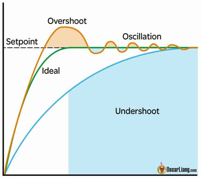
If your traces don’t look smooth but have lots of ups and downs, that’s called oscillation, and it’s an indicator that the signal is too noisy or your movements aren’t big enough.
The graphs on the right are also extremely helpful:
- Peak is highest amplitude of the overshoot (ideally the closer to 1 the better)
- Latency is the time it takes to reach setpoint (ideally the lower the better)

When D gain is low, you will get overshoot or even oscillation. As D gain increases, there will be less overshoot and Peak will decrease, but Latency will go up as a result. When D is too high (undershoot), the initial peak might not even reach the setpoint and this is not ideal. Find a response that has minimal overshoot and yet has relatively low Latency.
You can zoom in and see it more clearly (or select fewer logs, and hit Run again). We only need to look at Roll and Pitch axis.
In our example, it’s pretty clear the ideal value is orange (3) for both pitch and roll, so that would be 1.0.
It’s pretty common to have a different PD balance on pitch and roll due to the different weight distribution. If that’s the case for you, take the Damping slider to the position you want for pitch, write down the pitch D gain, then take the Damping slider to the position you want for roll, and adjust the Pitch Damping slider to match the pitch D gain you just wrote down.

Sometimes it’s better to be a little more conservative and avoid having D gain too high. If you are on the fence, always go with less D gain (a higher P/D ratio), so you can raise your overall PID gains higher at the end since D is usually the limiting factor.
What I’ve found is that the step response tool tends to be quite sensitive and the P/D balance might be lower than what I’d personally prefer. So I normally bump up P/D balance by 5-10% after finding an ideal value. That’s just my personal preference, you can give that a try if you want.
Drone size also affects PD ratio, larger drones tend to have higher P:D ratio. For example a 5″ might use 0.8-1.1 Damping slider while a tiny whoop might use 1.4-1.6.
Finding Max D Gain
Do the same test for Master Multiplier slider, move the slider in 0.2 steps. For a 5″ drone, start with values such as 0.8, 1.0, 1.2, 1.4, 1.6, and 1.8.

Be cautious and do not stand too close to the quad during this test. When D gain is too high, the quad may shoot up unexpectedly. Pay close attention to motor noise, and stop immediately if you hear thrilling oscillation.

You might notice that the shapes of the step response don’t change much between different values and that the Peak values remain roughly the same. This is because the response curve shape is mainly determined by the P/D ratio. Increasing the gains won’t significantly affect the response shape, but bumping up P/D gains can reduce latency.
You have reached the ideal Master Multiplier gain when one of the following occurs:
- Thrilling Oscillation: If you hear thrilling oscillation, you can’t increase D gain any further.
- Latency Plateau: If latency doesn’t decrease anymore (or very little), it means you have reached the upper bound tuning window. The motors are working at their hardest, and you are not gaining any more performance from them.
The maximum gain achievable is influenced by the noise level of your build and the amount of filtering used. Less filtering allows for higher PID gains. Sometimes, it’s safer to reduce the Master Multiplier slider by a notch or two once you find the maximum value. Avoid pushing D gain to the limit to account for potential issues like bent props.
Drones using higher cell count batteries (higher voltage) tend to require lower D gains. For example, on a 6S quad, D gains might be in the 30s, while on a 4S they are usually in the 40s.
In my example, 1.6 seems to be the value that gives the least amount of latency, with little improvement when increasing to 1.8.
If you can’t hear thrilling oscillations, use the Spectral Analyzer to plot D-term. As gains increase, motors may produce a thrilling sound peaking around 40-80Hz, especially when throttling up. If noise in this frequency range increases with higher gains, it indicates the onset of PID-related oscillations.
In this example, you can clearly see peaks around 60Hz for 1.4 (olive), 1.6 (green), and 1.8 (cyan). Although 1.6 shows latency improvement, I would not risk it and would likely choose 1.4 or even 1.3 to be safe.

There is ongoing debate on whether it’s better to have more D-term filtering and higher D gain, or less D-term filtering and lower D gain. However, never run with less D-term filtering and high D gain as this can lead to disastrous results if you hit an obstacle or bend a prop. It’s no joke, speaking from experience here:
After finding the optimal D gain, check setpoint tracking by plotting Gyro and Setpoint. The lines should be roughly parallel, indicating the quad is accelerating and decelerating at the same rate as the setpoint. However, there might still be a significant gap between them, indicating latency. In the next step, we will reduce this gap using Feedforward.
![]()
Tuning Feed Forward
Feed Forward (FF) accelerates your quad when you move the sticks, making your quad more responsive and closer to the setpoint. Unlike P term, which reacts only when there is a PID error, Feed Forward measures the rate of stick deflection. It gets the motors moving as soon as the stick moves, making it much faster than P term.
Feed Forward helps the quad respond promptly to stick inputs, providing a more immediate and controlled flying experience. It is beneficial for all flying styles, including cinematic flying, as it reduces latency between stick input and quad response.

When tuning Feed Forward I prefer to do some snap rolls and flips and check Gyro/Setpoint traces. Use your usual rate profile, or a default rate profile in Betaflight (just switch to an unused rate profile) to get a decent max rate at full stick. You can check my rates here: https://oscarliang.com/rates/#My-Rates
Instead of using the step response tool in PTB, use BE to check the setpoint/gyro traces. The gyro should track the setpoint more closely with less delay. Ideally, the gyro should be right on top of the setpoint.
If Feed Forward overshoots (gyro moves before the setpoint), the FF is too high. In the following demonstration, 0.5 is way too low, 1.0 is still not high enough, but 1.5 is a tiny bit too much and overshoots. I think Feedforward at 1.3-1.4 should do it in this example.
![]()
If the FF gain is too high, it can cause the P term to react in the opposite direction, trying to counteract it.

Doesn’t matter what your flying style is, feedforward can be useful and doesn’t apply only to certain types of flying. Even cinematic flying can benefit from a good amount of feedforward, if you are moving your stick smoothly and slowly, then feedforward won’t kick in anyway. When you need snappy response FF will reduce the latency between stick input and quad response. If you want smooth flying, just use expo, more RC smoothing or lower your rate.
There’s an optional setting, Feedforward boost (FF Boost). You want to increase it if gyro lagging behind setpoint at the start of a move, but catching up later on. But you should reduce it if gyro gets ahead of the setpoint at the start of a move, but falls behind later.
Tuning I Gain
The ideal I gain is largely based on feel. You don’t need a lot of I gain when you have optimal P and D gains; you just need enough to keep the drone from drifting and wandering. If you are cruising forward with minimal stick inputs, the drone should hold its position for a while. If there’s any drifting, then you need a higher I gain.
The I term in Betaflight has a REALLY WIDE tuning window, especially for powerful 5″ quads. Typically, a range of 0.5 to 1.5 on the I term slider works fine for 5″ quads. This wide window allows us to tune everything else first and adjust the I term last. With a high I gain, your quad will feel more precise, but if the I gain is too high, you may experience slow oscillations, which you want to avoid.
I found the step response tool in PTB is not effective for finding the I term, as the step response for pitch and roll remains identical regardless of the I gain slider value (e.g., 0.4 to 2.0). However, you can use it for tuning Yaw I gain, which I find usually lands around 1 on the slider for 5-inch quads.

You can tune the I gain by looking through the goggles and listening to the motors. If you aim to push the I gain as high as possible, try moving the I gain slider up until you notice slow bouncebacks and oscillations during fast moves, then reduce it a notch or two. However, it’s really hard to get our quads to show bouncebacks, thanks to features like “I-term relax” in Betaflight. Nowadays, you can use extremely high I gain without much negative impact (such as bouncebacks).
For 5″ quads, I usually just leave the I gain slider at 1.
With I-term relax, you can adjust the cutoff based on the drone’s responsiveness. For freestyle drones, you can usually leave it at the default setting. For racing drones, increase it to 30. For heavier drones like cinelifters and 7″ long-range drones carrying a GoPro, set the cutoff to 10.
Dynamic Damping
Dynamic Damping is a feature that boosts D gain to the maximum during sharp moves but does not increase it during normal flight. This helps in reducing motor heat. The problem is, when the drone detects a sharp move and trying to bump up D gain, it’s sometimes too late so it doesn’t always work. So I normally just leave Dynamic Damping slider at 0 and leave the Damping slider unchanged, the quad will use the same D gain through the whole flight. But if you have hot motors when doing freestyle, Dynamic Damping is worth looking into.
This is how I normally use Dynamic Damping:
- Note down your current D Max value. This value should be the same as Derivative because the Dynamic Damping slider is set to 0 at the moment.
- Begin by increasing the Dynamic Damping slider to 1.
- Then reduce the Damping slider until the D Max value remains the same as before, this will lower the baseline D gain used during normal flights to keep your motors cool. Don’t worry if you can’t get D Max back to exactly what it was before, 1 or 2 points difference shouldn’t be noticeable.
Dynamic Damping is also useful for making your drone smoother if you have vibration even with simple forward flights. That’s because vibration can be amplified by D gain, and using Dynamic Damping can suppress D gain when you are just cruising. However this is just a bandaid, you should address the mechanical issue first.
Other Settings
Anti Gravity Gains
Anti-Gravity (AG) gains help reduce wobbling and nose dips when you punch out and then let go of the throttle. AG temporarily boosts I gain during throttle pumps to mitigate these undesirable dips. However, if the AG gain is set too high, your quad may experience rapid oscillation (stutter) when you release the throttle, because AG boosts both P and I.
Default is 8, reduce it if you see wobbles during fast throttle changes. For 5″ freestyle drones, I found 8 to 12 a good range.
You can tune AG by looking in the goggles, or check for nose dip in Blackbox logs, and see the effect of anti-gravity.

Dynamic Idle
Dynamic Idle improves stability, enhances propwash handling, and reduces the chance of ESC desync. It increases motor speed when the throttle is at zero, improving control authority and responsiveness at low throttle inputs. Other benefits include sharper flip and roll stops, more responsive in low throttle and more effective braking.
When Dynamic Idle is set, Static Motor Idle (in %) in the Motors tab is disengaged.
To setup Dynamic Idle, you need to
- Enable bi-directional DShot in the Motor Tab (if you already have RPM filter enabled, you are all set)
- Enter a suitable Idle RPM value in the PID Tuning page (e.g., 20 to 40 for 5″ drones).
The recommended Idle RPM value depends on propeller size and pitch. Smaller and lower pitch propellers generally require higher values. Adjust the value higher in windy conditions to counteract instability.
Considerations for Dynamic Idle:
- High Value: Reduces hang time when the drone is upside down (motors push harder towards the ground). It can also make the quad hover slightly at zero throttle, making throttle management harder.
- Low Value: Risks low throttle instability.
Setting the Ideal Value:
- Determine ESC Idle Value: Default is usually 5.5%. Test your motor in the motor tab using a smoke stopper or bench power supply to limit current.
- Check RPM: Spin the motor at the ESC idle value (e.g., 5.5%, slider at around 1055) and note the reported RPM (requires bi-directional DShot).
- Set Dynamic Idle: Use the RPM value divided by 100 as the ideal Dynamic Idle value.
Throttle Boost
Throttle Boost increases your throttle value when you rapidly move the throttle stick up, giving you extra power. This can make throttle responses more dynamic but can also make them unpredictable.
- The Default Value of 5 generally works well
- Adjustment Tips:
- If you find the throttle hard to manage precisely, reduce the value.
- Some racers even disable Throttle Boost entirely by setting it to 0 to have the most predictable throttle response possible.
- Experiment with different values to see what works best for your flying style.
Voltage Sag Compensation
This feature reduces the maximum motor drive value when the battery is full and increases it as the battery voltage drops. It provides more consistent flight performance throughout the flight. But be careful it might make you forget when to land because the quad would feel similar through the whole pack.
Thrust Linearization
- Recommended Setting: Enable Thrust Linearization at 20%.
- Benefits:
- Boosts PID to improve responsiveness and control at low throttle.
- Lowers PID at high throttle to reduce oscillations (similar to TPA).
- Helps with nose dips and is especially useful for whoops and drones using 48KHz PWM frequency on ESCs.
Note: Since it boosts PID at low throttle, you might need to lower the master multiplier slider if motors get hot.
TPA
TPA stands for Throttle PID Attenuation.
To fine tune TPA, perform a throttle sweep and check the frequency vs. throttle heatmap. If you get oscillations above a certain throttle level, in which case TPA can help.
In the latest Betaflight it only attenuates D gain above certain throttle level (which is usually the cause of the oscillations). In the older Betaflight it attenuates both P and D, if you want you can bring this back by typing in CLI: set tpa_mode = PD.
Normally I prefer to set throttle value in TPA as high as possible, so D gain is more constant across a wider throttle range. Make sure to set the throttle value a little lower than the position where the D term related oscillations start to show up. For example, if oscillation starts around 1800 throttle, I would do something like this: TPA = 0.75, 1750.
I Term Rotation and Absolute Control
These features are generally not needed for FPV freestyle drones and are more beneficial for line-of-sight pilots.
Tuning Yaw
Yaw generally doesn’t require much tuning as the default gain works well. The tuning window for Yaw is quite wide. Unlike pitch and roll which are based on thrust generated by propellers, yaw is based on the inertia generated by propeller rotation. Therefore, yaw will inherently be too slow to overshoot setpoint, and there’s little need to tune yaw PID.
Yaw is also too slow for D terms to have any meaningful effect and it’s generally not required. However you can enable it if you want, but it might introduce more problem than it solves, like vibrations etc. So we are left with P and I terms for Yaw.
You can tune Yaw using the step-response analysis like we did with Pitch and Roll. Additionally, if slow oscillations occur in the back part of the graph, then I-Term is too high. If fast oscillations occur, then P-Term is too high.
If you have yaw shakes when doing throttle pump, you can isolate yaw from the slider tuning, and set Yaw PID individually. To do this, go to the PID tuning tab, in the ‘Slider Mode’ dropdown list, select RP (Roll Pitch), instead of RPY (Roll Pitch Yaw). This will exclude yaw values from the sliders, and allows you to enter PID numbers for yaw. For 5″ freestyle and cinematic builds, try 100 for both P and I would be a good starting point. You can also try higher values as yaw tends to be quite slow reacting.
There is no perfect tune
How good is good enough? You can always spend more time playing with filters and PID numbers, and you may see improvements but it can be situational and the time you invest in it might not be proportional to the result. I normally just stop when it looks “good enough” and leave it there unless there’s a specific problem to be solved
Troubleshooting Tips
Defective Gyro
A 5-inch FPV drone should fly smoothly on default Betaflight settings. If your quad experiences vibrations, it could be due to mechanical or electrical issues, or sometimes a bad gyro on the flight controller (FC). Here’s how to diagnose a defective gyro:
- Symptom: One axis is significantly noisier than the others, especially in the lower frequency spectrum below 200Hz.
- Diagnosis: Rotate the FC by 90 degrees. If the noisy axis follows the rotation, the gyro could be faulty.
In the example below, the pitch axis is much noisier than roll and yaw, with bursts of D term noise caused by the noisy gyro. Potential Causes:
- High power wires near the gyro.
- Noisy power supply to the FC.
- Poor board design.

Solutions:
- Removing any high power wires near the gyro .
- You can try using a 1000uF low ESR capacitor at the ESC power.
- If already using a capacitor, try soldering an additional smaller 220uF-470uF capacitor to the power of the FC (VBAT/VCC pad).
- If none of the above suggestions works, you might just have to replace the FC.
RC Smoothing
RC smoothing is essential in Betaflight to avoid issues with feedforward. Proper RC smoothing settings depend on your RC link. It’s best to load the appropriate RC_Link preset to avoid mistakes.
The Auto Factor is perhaps one of the most important values, lower is more twitchy and responsive while a higher value is softer and smoother but more sluggish. Here’s a general rule I personally follow:
- 20-25: Racing
- 30: Default value, great for Freestyle
- 50: Cinematic
- 90: Extremely smooth cruising, delay might be noticeable to some
- 120: Highest smoothness possible without getting into trouble, but delay is noticeable
Bad gear/pilot require higher RC smoothing too, e.g. Low quality radio control equipment, worn out gimbals, pilots with shaky fingers, etc. Basically anything that might contribute to jerkiness in RC commands.
If possible, check black box logs to confirm you have smooth setpoints, if the setpoint isn’t smooth (has steppings from RC commands), simply increase the smoothing slightly.
If you have noise in setpoint that peaks around 50Hz, 150Hz, 250Hz or 500Hz, then there is probably a problem with RC smoothing. These frequencies are common packet rates in RC link. In this example, it’s Crossfire 150Hz.

If you are not using enough filtering for the RC commands, you might not have smoothed out the RC signal enough and it could create noise at the frequency of your radio link packet rate.
RC smoothing removes stepping and bumpiness in your set-point, it makes P term trace less jerky. However it also adds delay to feedforward as well as setpoint, so your quad might feel a little bit less responsive. RC Smoothing is useful, but too much smoothing defeats the purpose of having fast RC packet rates like ExpressLRS offers.
The goal is to smooth out the steppings but not adding too much delay. If you want smoother RC input, try adding some more expo, it has similar effect but it won’t give you the latency penalty.
The best way is to just load the appropriate RC Link preset as I talked about here. If you failed to load the correct RC_Link preset for your particular RC link and packet rate, it might also cause problems to Feedforward. In this example, feedforward jitters due to the lack of stepping smoothing in RC commands.

PID Sum too low?
If the PID_Sum hits the default 500 limit (50%) because PID settings are very high, you can raise the limit to 1000. To do this, enter the following command in the CLI: set pid_sum_limit=1000. But it does not always make a difference in flight behaviour as motors might saturate at this rate anyway.

ADC Filter Jitters Causing Oscillations
If you experience random vibrations and wobbles due to feedforward jitters, even after applying the correct RC Link preset or increasing RC smoothing, the issue could be due to the ADC filter.
Ensure the ADC filter is turned off in your radio’s system menu under the hardware page.
Feedforward spikes appear in the Blackbox logs when the ADC filter is turned on, causing unwanted oscillations and vibrations.

Edit History
- Nov 2022 – Guide created
- Jun 2024 – Updated to Betaflight 4.5
62 comments
v26.05.0 version of PIDscope (OpenSource fork of PTB) has landed github.com/dzikus/PIDscope/releases
Many new features implemented basing on PRO tier of PTB.
Great breakdown of PIDtoolbox + Blackbox Explorer, Oscar — the section on identifying D-term oscillation versus filter delay is the cleanest explanation I’ve seen anywhere.
One thing readers might find useful as a complement: there’s now an automated approach where a neural network reads the same blackbox features (gyro FFT, step response, filter response, prop wash signature) and outputs a CLI-ready PID/filter set in around 30 seconds. We open-sourced the model and a hosted version is at fpvtune — it’s not a replacement for the diagnostic depth PIDtoolbox offers, but it’s a much faster way to get a sane baseline before you start manually iterating, especially for unusual builds where Betaflight defaults are off.
The thing your guide nails that the auto-tune approach can’t is teaching pilots to see what’s actually wrong. Anyone who skips that step ends up cargo-culting tunes from YouTubers without understanding why their motors run hot. So I’d argue the right workflow for most pilots in 2026 is: auto-tune to baseline → fly → look at PIDtoolbox graphs the way you describe → adjust manually from there.
This is hands down the best PID tuning guide out there. I’ve been flying FPV for about 3 years now and always struggled with the Blackbox analysis part – the PTB graphs were intimidating at first.
One thing I’ve been experimenting with recently is using automated blackbox analysis to get a starting point before manually fine-tuning with the method you describe here. I found a tool called FPVtune (fpvtune.com) that analyzes your blackbox logs and suggests PID values using neural networks. It’s not a replacement for this kind of deep manual tuning, but it gives you a much better starting baseline than Betaflight defaults, especially for unusual builds.
For anyone who finds PTB too complex (or now that it’s gone paid), having an automated analysis as a first step and then using Oscar’s method here for the final polish is a really solid workflow. Thanks Oscar for putting 200+ hours into this – it shows!
New PIDtoolbox fork for Octave that works out of the box
https://github.com/dzikus/PIDscope/releases
thanks, tried to do this with youtube videos without success, this guide is amazing, can i use the same steps with inav?
A big thank you, it’s been 6 months since I started FPV and your work helps me a lot. I’m still in the process of getting the hang of this tutorial, but at least I have a solid foundation.
Thanks, my friend.
Hello, Oscar. I really like all the tutorials on your website, and I have translated all of them into Chinese. Thank you very much. I have a question and would appreciate it if you could explain it to me. When we adjust the D gain slider and then directly adjust the main multiplier without touching the PI sliders, does this mean that for PD balance, we only need to adjust the D slider? Then use the main multiplier to amplify this PD balance?
To adjust PD ratio, you can either use D gain slider or PI slider, it’s up to you which slider to use, you can use both you want. Master multiplier does not change the ratio between P, I and D, it only increases these values while keeping the ratios the same.
PTB looks like it went pay-to-use. Is there any free software that can do the stuff PTB can do? Thanks
someone posted a link below in the comment to an old version of PTB which is free, I am not sure if the link still works i haven’t tested it myself.
What PID stands for? Thank you
https://oscarliang.com/pid/#Understanding-PID-in-FPV-Drones
Hello Oscar!
How big should the delay be to be worth spending time and effort to try to reduce it even more by reducing filtering? I have a Gyro and D-term delay of 2.5ms. Should I keep “playing” with sliders to reduce it even more, and will it affect the flight quality, and will it give an opportunity to raise PID gain? Thanks!
Those numbers are not very accurate I found and can change with the movement of the drone.
Measuring the delay between gyro and gyro_scaled traces are more accurate: https://oscarliang.com/blackbox/#Measuring-Gyro-Filter-Delay.
You can never get filtering “perfect”. A little difference in your props (types, conditions), even in the weather condition can throw off your filter tune. Get it to a state which it feels great to fly, and that would be enough IMO. Spend more time flying, that’s how you know whether your quad flies good or not :) Graphs are just graphs after all.
Yes indeed!)) Thanks for the tip! Even PTB can show different delay estimates with the same settings.
Dear sir, do you have a copy of PIDtoolbox for mac, i have been unable to locate one, thanks sir…
Unfortunately I deleted it once i installed on my computer.
Quite disappointing that the author removed the installers all together (even for the old versions), now you have to pay to use it. Let me know if you find a way to download it.
I have the same problem now. After a hard drive failure I lost this software, if I had known the author would take such steps I would have made a backup copy of the installer :(
Unfortunately, the code left on github in version 5.58 also has a few errors and does not load files from BF 4.x.x.
I have Matlab purchased from my company and I will try to improve the code and prepare a version for Windows. Unfortunately, I have to check whether the license I have allows installing Matlab on Mac OS, unfortunately in the Windows version I can only prepare a file that works on Windows :(
It is not right that the author removes previously released versions and forces people to buy them. I understand that someone wants to earn money, because work costs money. However, when we decide to write software, it is worth considering whether we do it for free or commercially. This is how you first use free software testers in the community (in a commercial approach, such people must be employed), and then cut them off from the software.
I found a copy of the PIDToolBox installer 0.65 somehow, maybe you can give it a try: https://drive.google.com/file/d/1liuUWdpHAs8T5-gCJBalD8n9fRCBTkHe/view?usp=sharing
I also found a similar tool (https://bucksaw.koffeinflummi.de/), but it’s still WIP, and not on par with PIDToolBox in terms of features. Once it becomes a good alternative i shall update this guide.
If anybody needs the 6.5 for windows there is a copy still available on github here: github.com/gabrieldev6/pidtoolbox-v65 . But support the author if you can obviously!
cybershafarat.com/wp-content/uploads/2024/01/PIDToolBox.zip
here’s a windows download if anyone is interested
what you mean:
on a 6S quad, D gains might be in the 30s, while on a 4S they are usually in the 40s.
30s – 40s ?
30s = 30-39
40s = 40-49
> “it’s ideal to have the overall noise floor below -30dB above 50Hz”
Question: Pre-filter or post-filter?
Thanks Oscar. This is the most comprehensive and helpful article about this topic.
Post filter.
do you mean :
The spectral analyzer in PTB uses decibels on the Y-axis,
pitch axis ?
I think you are the greatest informer off the Fpv World.
Been reading your pages for years. Truly appreciated.
Thank you.
Amazing tutorial! thank you very much! got a quick Question, i have Speedbee F7 V3 witch has BMI270 at 3.20 kHz Gyro(due to BMI270) and 3.20 kHz PID loop, do i still need Gyro lowpass2 ON at 1000Hz? its in normal mode. not sure if its best to leave at normal or option2 also :( thanks a lot
Same rules for 4K looptime applies to 3.2K too – which means you should at least leave GL2 on at 1000Hz or lower.
thanks a lot Oscar, you rock!!!
i will leave GLP2 with 1000Hz then, this one was tricky beacause both are 3.2khz but that F7 FC supports 6K(Around that) but due to BMI270, its stick to 3.2… hehe thanks a lot again :)
I’ve been looking for everything on the subject for days to soak it up. Here I found everything important, short and crisp, on one page. It couldn’t be better. 10 points out of 10. Thank you very much!
Hey Oscar awesome tutorial! I only have one question, you don’t talk about dynamic damping (D max) at the end of the tune! Should we keep it to 0? Or put it back to 1?
Thanks keep up the good work, it’s really helpful for us beginner in the hobby
Increasing it might improve propwash handling, but it also increases the chance of hot motors when you have bent props. You can try increasing it by analysing blackbox logs and determine the highest D gain, or do some test flights while increasing it step by step. But if you want to skip all the trouble, you may also just leave it turned off.
I have an issue where 6S I have flyaway problem (with about 15-20%) when all the PIDs slider are in the middle (BF 4.4.1) but when using a 4S battery it is completely fine, using all the slider in the middle. I have a Panasonic FR 1000uF 35v with a TVS pcb on the XT60 connector and a Panasonic FR 680uF 35v on the ESC.
here is the built:
Frame: GEPRC Mark 5 Pro
FC: Diatone Mamba F743 V2 (BF: mambah743_2022b)
ESC: Diatone Mamba 65A 128bit (AM32)
Motors: T-Motor F60 Pro V 2020KV (Rated for 6S use)
VTX: O3 AU
GPS: HGLRC M10 Mini
BF: 4.4.1
I am not sure what else to check for, please help
sounds like it’s just too much noise for the gyro to handle. do you have any blackbox logs?
I have figured it out after talking several people in BetaFlight’s Discord and also talking to Diatone.
I was able to fix the issue by lowering the Throttle Boost from 5 (default) to 2.
I am in contact with T-Motors to find out why that is.
Hopefully this will help your readers in the future.
Dear Oscar
Thank you for your perfect guides, wish you the bests for rest.
I made a clean setup and after RPM filter and Notch filter there is still some noise that i cannot understand what it can be.
here is the PTB picture
drive.google.com/file/d/1HuuFiJVSr3DlUEfJUx180LrUyBoK8hlN/view?usp=sharing
there are some noises between 60-80% Throttle
I just fixed the noises inside the green box with Dynamic Notch Filter
But i do not have any idea about the Blue boxes.
can you please give me some hints ?
Can you try setting ESC PWM frequency to fixed 48KHz ?
Hi Oscar. Same issue here. Already got a bluejay and 48KHz. No matter what i do, there is D-term noise on the pitch axis. Starting at about 80% of throttle. TPA breakpoint is set to 1750 following our manual. Need a good advice to proceed with tuning. Maybe you can have a look at my logs? drive.google.com/drive/folders/1xGhf2QT8Yl5rImajzVKkBd5Z-FlE5paB?usp=drive_link
Captured on BF defaults, just RC link configured- ELRS 250 for freestyle.
You are actually reducing filtering for high throttle oscillations by setting TPA higher to 1750. I think you should just leave it at default if you do have high throttle oscillations, the default is a good starting point.
There’s a more serious and concerning problem with your build, the radio link is actually dropping packets! If you check RC Commands in Blackbox Explorer, you will see the sudden dips of RC commands. I think you should fix this before looking at PID/filter tuning. This could also partly contribute to your noise issues.
Great great article!
But I can not find the cause of the periodic twitches of the copter.
Video demonstrating the problem: youtube.com/watch?v=HadMNNDLi5k
Flight time:
02:11
02:46
There are logs. Where to look?
maybe share your logs on google drive and let’s have a look?
Another good place to get troubleshooting help is https://intofpv.com/
Thanks!
Log: drive.google.com/file/d/1OKZHyLf–fhArrWftB23HvbaaIyu4Jar/view?usp=share_link
This is the log from the flight, which is in the video above.
There are some spikes in your RC commands, which I believe is causing some spikes in your feedforward and results in the twitching.
Have you disabled ADC filter in your radio? See second step in this section: https://oscarliang.com/pid-filter-tuning-blackbox/#Basic-configurations
I suggest you to go through the whole “Basic Configuration” again.
ADC filter enabled.
Thank you! I will try everything you said, but queues.
1) applied presets, as in your article.
2) disabled the ADC filter.
The problem remains, but perhaps not such severe fluctuations now.
I did the following: in the “TX Power” settings: “Dynamic” ~ off; “Max power” ~ 100. As a result, the problem is completely gone! When there was a problem, the settings were as follows: “TX Power”: “Dynamic” ~ dyn; “Max power” ~ 1000. Apparently the problem is related to power switching on the equipment. Hardware: built-in elrs 1000mw jumper t-pro.
Of course, I will think about how best to make the antenna on the receiver. What else can be done?
Can you use 500mW? I don’t think 1000mW and 500mW make a big difference when it comes to range. Also have you tried disabling Dynamic Power?
With dynamic power, a problem arises – the copter shakes when turning. With static power, there is no problem.
Yea just disable dynamic power, I always have it disabled.
OK, thx Oscar!
Great thanks for all these deep explainations, details, so easy to follow!.
I have started to optimized on Tyro79 with a Mamba Mk4 F722 FC.
As the first steps are “only” optimizing the signal fitering, perhaps one only flight with several filtering simulation (to do in a dedicated app or other) could be enough instead of performing one flight/record per parameters setup?
What do you think about it?
I subscribed to your patreon!
The help provided by these articles is tremendous!
I often come here and it’s generally better than videos and especially more complete!
On the other hand you do not use the method of first putting the master to multiply the farthest and then making the other parameters (like Chriss Rosser and others). Why ?
Continue like that !
Just a matter of styles I guess, I don’t think that would make much of a difference to the final tune. But if change Master Multiplier first, then you don’t really wanna use the Damping sliders later on, as it will change your D gain, instead you wanna use the P/I slider to change P/D balance.
Like I said, either way we are doing the same thing and you will get the same result.
Thanks ! :-)
Drone falls from the sky.
Desync or power loss?
Can you see it in blackbox?
thank you
Yes it’s possible to tell.
Amazing article!! Thank you!!
Seriously amazing work.
I still recommend 48kHz PWM on the ESC for this particular setup (running dynamic idle AND thrust_linear basically negates the only downside, and higher PWM frequency really helps reduce EMI coming off the ESCs and ‘seen’ by the flight controller gyroscope).
In Betaflight 4.4 the AntiGravity feature will have different values, but stock works extremely well – generally running 10x the previous value if you took the time to tune it should work great.
Thanks for the great feedback and recommendations!
I’m having trouble tuning a racing build because my gyro has a constant spike at 40- 80 hz and I cant seem to get rid of it, it mostly shows up on roll peaking at 5 db (on pitch and yaw it only peaks to -10 db) is this a bad gyro?
I’ve checked and made changes multiple time but nothing seems to fix it. the build is running 6s with the rush pfb that has 2 35v 330uf caps and 3 Tvs diodes if that helps
Any help is appreciated!
Thanks
Try to rotate the FC by 90 degree and see if the noisy axis becomes pitch? if so then it’st most likely to be bad gyro.