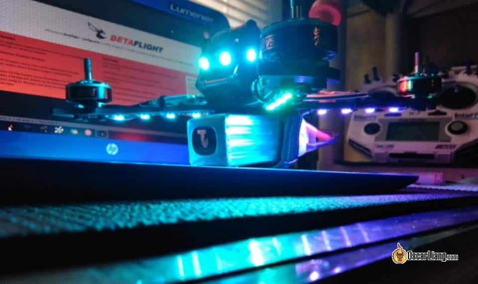
Adding RGB LED strips to your FPV drone isn’t just visually appealing—it offers practical benefits too. It can help you easily identify drone orientation, monitor battery status, and indicate flight modes and many more. Betaflight makes this setup straightforward. In this guide, I’ll walk you through the process step-by-step.

For more tutorials, check out our comprehensive Betaflight setup guide: https://oscarliang.com/betaflight-firmware-setup/
Table of Contents
Benefits of Adding RGB LED to FPV Drone
Adding RGB LED strips to FPV drones offers several practical and aesthetic benefits:
- Improved Visibility and Orientation: LEDs help pilots quickly determine drone orientation when flying in line of sight (LOS), making it easier to navigate in low lighting conditions or long distances.
- Battery Voltage Monitoring: LED strips can visually indicate battery status in real-time by changing colors based on voltage levels, helping pilots easily monitor battery life without constantly checking telemetry or OSD.
- Flight Mode Indication: RGB LEDs can display distinct colors for different flight modes (e.g. acro, angle, horizon), providing immediate visual confirmation of your current mode.
- Enhanced Safety: Bright LEDs significantly improve the visibility of the drone to spectators and other pilots, reducing collision risks.
- Customizable Appearance: LED strips allow you to personalize your drone, creating a unique appearance during flights, especially useful for racing, freestyle, or group flights.
- Night Flying: Enables safer flights in low-light or night time conditions, greatly improving visibility and drone tracking.
- Race and Event Identification: In drone races, distinct LED colors help pilots and spectators quickly distinguish between multiple drones.
- Many Other Functions: Explore Betaflight’s LED tab for more features and creative uses.

What You’ll Need
The LED strip feature in Betaflight is primarily designed for addressable RGB LEDs such as WS2812. They come in various forms. The most common is a flexible strip sold by the meter, easily cut into individual LEDs or smaller segments with scissors for a perfect fit. Ensure you select the 5V version:
- AliExpress: https://s.click.aliexpress.com/e/_okHypsi
- Amazon: https://amzn.to/4n3aSfk
Alternatively, consider RGB LED strips specially designed for FPV drones. These come mounted on a PCB, simplifying installation:
- GetFPV: https://oscarliang.com/product-x6wf
- RDQ: https://oscarliang.com/product-dxea
- AliExpress: https://s.click.aliexpress.com/e/_onDTglu

Other Tools and Hardware
Here’s a checklist of additional hardware you’ll need to add RGB LEDs on your drone:
- A flight controller that supports RGB LEDs (look for a solder pad labeled “LED” or “LED Strip”). See our FC recommendations.
- Supplies to mount the LEDs to your drone, such as double-sided tape, zip-ties, or clear heat shrink. Check out our tool recommendations.
- Small-gauge electrical wires, 28AWG or 30AWG should suffice.
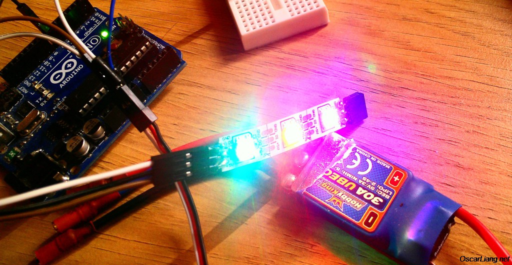
Power Requirements
A single 5V WS2812 LED typically draws around 18mA. Ensure your flight controller or BEC can supply enough current for the number of LEDs you plan to use. Current draw varies slightly with color—when it’s showing blue light it typically consume more current than when it’s red.
The power consumption of LED strips is negligible compared to motors, so they shouldn’t noticeably affect flight time.
For your reference, here is the current draw for 3 LEDs.

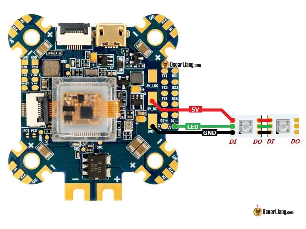
Step 1: Connect LED to Flight Controller
Most Betaflight flight controllers have a dedicated pad labeled LED or LED Strip.
Connect the LED strip as follows:
- 5V → 5V
- GND → GND
- DI (DIN) → LED
Note: most WS2812 LED strips are directional, with a data-in (DI) and data-out (DO) pin. Connect the flight controller’s LED pad to the DI pin on the LED. If adding additional LED or LED strips, you can connect them in series (connect DO of the existing LED to the DI of the new LED). Each LED will be addressed when connected in series, and you can control/program them individually. There’s a limit though, you can only control up to 32 LED’s in Betaflight.
Pro Tip: When soldering, use a low temperature and avoid holding the soldering iron on the pads too long, as overheating can damage those LEDs.
Step 2: Mount LED Strips
Ensure solder joints are insulated from your drone’s carbon-fiber frame.

Securely attach LED strips so they won’t come loose due to vibrations or crashes. Note each LED’s wiring order and location.

Step 3: Enable LEDs in Betaflight
Before connecting a battery, always remove propellers for safety.
Open Betaflight Configurator and connect to your drone.
Navigate to the Configuration tab.
Scroll to “Other Features” and enable LED_STRIP.
Click Save and Reboot.
After reconnecting with a battery, the LEDs should illuminate white by default. The LED Strip tab will now appear on the left menu. If not visible, enable Expert Mode (top-right).

Step 4: Setup LED Strip Layout
Click on the LED Strip tab.
Activate “Wiring Order Mode”.
Assign LEDs sequentially on the grid, starting with the LED closest to your flight controller.
The grid helps visualize the arrangement but the exact placement isn’t critical.
Betaflight starts numbering with 0 so when we get to the 4th LED the number is 3.
Complete for every LED, then disable Wiring Order Mode.


Step 5: Assign Functions to LEDs
Assign colors and functions to LEDs:
- Select the first LED (numbered 0).
- Under Functions, select Colors and pick your desired color. The LED on the grid will have indicator showing Function and Color have been selected.
- Repeat for each LED.
- Click Save. LEDs will now display the chosen colors.


Basic LED Setup
Let’s move on to a simple example.
Here I have entered the first 4 LEDs – that’s a LED strip I will be mounting on one of the arms.
Again, it doesn’t matter where on the grid, as long as you have room to enter all the LEDs and can make sense of where they relate to their position on the quadcopter.

Here I will place the rest of the LED’s in the grid, then deselect the Wiring Order Mode button. Notice that I have 6 separate strips, and the order represents how they are wired together in series.

Now we can start assigning functions to each individual LED. In this case we are just going to assign different colors for them.
Highlight the first LED (numbered 0) by clicking on it, select “Colors” from the “Functions” drop down menu.

Then click any color you want to assign that LED in the color chart.

Do the same thing for the next LED and so on until all the LEDs have been assigned a color.

Click the Save button and the LEDs on the quadcopter will switch from white, to the colors you’ve selected.
Betaflight LED Setup: Advanced Functions
The LED feature in Betaflight is pretty powerful, there are many functions that can be activated and overlaid for a completely customized LED display.
Color modifiers, Blinking, Larson scanner/Knightrider effects, warnings for battery, RSSI and more, even color coded VTX channels controlled through SmartAudio. The possibility is exciting :)
The throttle modifier will change the LED color depending on throttle position. The color selected will be shown at mid throttle, the previous selectable color will show at low throttle and the next selectable color at full stick.
To activate this, highlight the LED you want to use and click the Color Modifier for Throttle. This can also be changed from throttle to a different channel such as AUX switches for flight modes, rate modes etc.

Note the orange dot indicating Throttle Color Modifier.

Both rear arms set to change color according to throttle position. Once saved this can be tested through the transmitter without arming, simply slide the throttle up and down and see if you like the transition.
Turn indicators will flash corresponding LEDs when roll or pitch is applied. To do this, first we must select the orientation for the specific LED we want to use by selecting N, S, E, W or UP and DOWN.

Notice the orientation arrow attached to that LED box now

Next click the “Indicator” switch. Do this for any LED you would like to blink when TX input is applied in that direction.
Now this LED will blink when left roll is applied, slow with small inputs and fast like a strobe when at full stick. This can also be tested now with the transmitter.
Arm State is another useful function. Highlight the LED you wish to use and select Arm State from the Functions drop down menu.

The Arm State function allows you to select two colors, one for when armed and one for when disarmed.
There are so many combinations that can be made here to get that custom look you’ve always wanted, start playing around with different settings and see what happens. Wether you would like to add some lights to help orientation, light up the entire night sky, or just add a touch of color for your race, LEDs are always cool. ;)


Here is a instructional video by Droneofprey.
Turning LEDs Off Using a Switch
You can assign an AUX switch to toggle LEDs on/off: go to Modes, enable LEDLOW, and assign it to a preferred AUX channel.
Troubleshooting
- LED not lighting up: Verify wiring and soldering connections. Ensure Betaflight configuration matches your wiring.
- Incorrect LED function: Double-check the LED strip assignment and functions in Betaflight.
Final Thoughts
A properly configured LED strip on your FPV drone is both functional and visually impressive. Experiment with different setups to best suit your flying style and needs. Enjoy your enhanced FPV drone experience!
Edit History
- Jun 2018 – tutorial created
- Jun 2025 – updated
35 comments
Thank you Oscar.You is Magic❤️💪
How to use led of speedybee master 5 V2 frame
My FC doesn’t have an LED data pad. Am I able to remap a TX pad to control the LED strip? I tried mapping led strip to the tx4 pin but nothing happened.
One quick question if I may… I have PandaRC Programmable RGB FPV Drone LED Lights Strip and my FC is Rush Blade F722 Digital (only one LED output pad). As per your picture here: https://oscarliang.com/wp-content/uploads/2018/06/mounting-ws2812-led-on-mini-quad-under-arm.jpg – I’ve noticed those LED strips inputs and output have all the wires connected, even GND and 5V to all outputs. I’ve heard that only signal/data wire needs to go in serial from the FC to the 1st LED strip’s input, and then from its output to the next LED strip in line, and then from that LED strip’s output to the next LED strip’s input, and so on… GND and 5V wires can be connected from the FC to each LED strip’s input only. Not sure what would be the best thing to do, I am just worried there will be a mess of wires if I have to connect all of them to all inputs and outputs on the LED strips. What is your valuable opinion what to do when there is only one LED output on the FC like on Rush Blade F722 Digital? Maybe to connect only one LED strip then, but then I can’t have all my quad’s arms lit, and I wanted every arm to have one LED strip attached to the bottom :( Here is my wiring diagram, am I correct with these connections? https://i.imgur.com/z76nZff.jpeg – Thank you so much in advance!
You wiring looks about right. But do you need to control every single LED individually? If not, then you can just split the LED_Strip pad to all 4 strips, and not having to route around with wires. In this case all 4 strips would be displaying the same thing.
Hi Oscar, and thank you so much for your quick reply. I am so sorry, I’ve lost you for a moment… I do have 4 LED strips, and each strip has 4 LEDs on it. I wanted to install them on my quad’s arms just like in the diagram I posted in my original message up there. No, I don’t need each LED to be controlled independently, I don’t even need each strip to be controlled independently. All I want is to have each arm with one LED strip attached to it (4 LED lights), and as far as I am concerned, what one LED strip with 4 lights does, all other 3 can do the same, I don’t care. When you said “…𝘵𝘩𝘦𝘯 𝘺𝘰𝘶 𝘤𝘢𝘯 𝘫𝘶𝘴𝘵 𝘴𝘱𝘭𝘪𝘵 𝘵𝘩𝘦 𝘓𝘌𝘋_𝘚𝘵𝘳𝘪𝘱 𝘱𝘢𝘥 𝘵𝘰 𝘢𝘭𝘭 4 𝘴𝘵𝘳𝘪𝘱𝘴…”, did you mean, I could connect all 4 LED strips to the same Rush Blade F722 Digital LED output pad? Basically like parallel? I was just concerned if that would be too much for power draw for the FC?
Yea, you can connect all 4 strips to the same LED output pad if it makes the wiring easier for you.
It doesn’t draw any more current from the FC, the LED output pad is just a signal, the LED’s get power from the 5V.
Amazing! Thank you so much Oscar! I’ve been asking this everywhere and not a single person explained it as clean as you did. Thank you a million! Rush Blade F722 Digital has BEC Output of 5V/5A 10V/3A, so that should be plenty for this simple configuration. I am totally OK with parallel, I actually want all 4 strips to do what 1 does. Instead of 16 addressable/programmable lights (4 lights on 4 strips), I will have 4 only (since each LED strip has 4 lights on it), and I am totally OK with that. If I want, I can use 4 different colors, I can have Larson effect on one and it will affect all 4. I want them all to be the same, so totally fine. Here is my diagram, please have a look if I got it right. Thank you so so much! You have no idea how much easier you make our FPV lives. Invaluable opinion and super polite and down to Earth person. Thank you! Link to my parallel diagram image: https://i.imgur.com/YuIWqiX.jpeg
Looks good to me!
SEII-FPV what software you use for draw diagram?
Can you have different setup/led layout on a switch i mean different profile that change with the active aux
Is there any way to configure the LEDs when using a control board or LED PDB? I haven’t seen anything on the net about utilizing a control board and still able to have the same customization as a single strand tethered together by a single data wire..
I’m wondering about the TinyLED PDB power board in particular.
So is there a way to just turn them on and off with an Aux channel? or change color from an independent aux switch?
Here’s how to do that:
Enable color modifier for all leds you want to be affected.
Select the aux channel you will be using. Let’s say you are using a 3 position switch on aux 4.
Set up your switch to control aux 4 in your radio.
Choose any color from the palette except the first or last color. This will be the color that is displayed when your aux channel is in the middle position.
Double click on the color to the before (to the left of) the color you selected and change the values with the sliders until you have the color you want. This will be the color when the aux switch is low.
Do the same for the color after the center color and this will be your aux high color.
If you want the leds off for one of the positions, just double click on the color and set all values to 0.
Hope this helps!
Greg, what if i want to use a momentary switch on my zorro to scroll through 4 colors for my tiny trainer (red, green, blue, white). i have the switch set up so is there a way to assign the color to a particular range on the aux channel? essentially, it’s a 4 position switch instead of a 3 so really there’s no “middle” position.
How do I wire multiple of these? I only have one led strip connector on my FC…
is there a way to turn on/off the LEDs completely via a Switch on my Transmitter ?
Can anyone help me with my crazy WS2812 LEDs? I have the Matek WS2812B programmable LED strip on my quad. It’s an Emax F3 Magnum Mini F.C. The LEDs work FINE if I have ANYTHING with 5 volts plugged into the USB port on the F.C. when I connect the battery, and then disconnect the USB. If I just plug the battery in, with nothing in the USB port, the strip will NOT light. But it works fine if I pull the USB plug out after the battery is plugged in. Weird?? Anyone have a clue?
Hi I would like to know if you have solved your problem with tez LED Matek since I have the same concerns as you? Thank you in advance see you soon
No, I haven’t. I have simply resorted to bringing a small USB battery bank, and a USB micro cord with me, and plugging it in before I connect the main battery, and then unplugging it. It’s a little extra work, but my lights function this way. ??
Hi, I will try to see about fixing it on my own, but i programmed all of my LED’s in beta flight to be solid color w/ directional lighting, and they worked for a bit, but one night i showed my friends what i was doing and i left without disconnecting from beta-flight. After coming back to fly the drone one strip (5 LED’s) wouldn’t properly follow what i programmed them to do, and they went wonky. Some were white, one light blue, another light pink, and the other side did exactly what i wanted them to do. After looking this up for a month i still cant find a fix or anyone else that has had this issue. I have the Eachine Wizard x220s that came pre-built out of box other than prop attachment. If anyone can help i would be grateful.
Hi,
For my flight stack F722 Mamba, there are 5LED pads. How do I go about programming them if I’ve soldered multiple LEDS to multiple LED pads? Currently BF config only changes colour of one LED pad and the rest are default red light
I’m not using strips, but each of my ESC’s has a factory RGB led attached. So far I haven’t gotten them working- do they use the same interface somehow?
The LED built into the ESC are configurable in BLHeliSuite32.
There is an option called LED: https://oscarliang.com/betaflight-blheli-32-esc/
Hey Oscar, love your blog! Is there a way to set up an aux switch to shut off the leds in betaflight? And what is the LedLow mode in betaflight?
I hooked these up on my f405 std( – to -, + to +, led to DI) configured it on INAV, save and rebooted, plugged in my lipo and no lights. What have I over looked?
Thanks!!
HI Oscar!!!
i have the wizard ts215 wich has 4 pin for led strips as you can saw at it’s manual
files.banggood.com/2018/04/TS215-MANUAL.pdf
In wich pin shold i wire my led strip? led in or led out?
Hey Oscar.
Is it possible to wire led strips in parallel?
I mean the same pads to two strips. Then I should have the same setups for both strips.
I asking about this because when I solder in this way one strip is working correctly and second changing colors like a mad. Do I need to do something in addition? Maybe I can’t split the signal for two strips?
Thanks
You should connect these LED in series only due to the nature of SPI digital signal controlling the colros.
For power yes, but the signal has to be in series if you want to program them all separately, otherwise you can end up with LED strips doing the same thing.
Thanks for the write up! Got my LEDs running in less than 10 mins after reading this.
To add to this, as I didn’t see it mentioned, is that you can CTRL-Click multiple LEDs to change their function all at once.
Maybe this wasn’t available before but it is on Betaflight Configurator v10.3.1.
My FC doesn’t have an LED data pad. Am I able to remap a TX pad to control the LED strip? I tried mapping led strip to the tx4 pin but nothing happened.
Hey Oscar, you can only change to all LED colors by AUX Position Switch, if you choose “Arm State” with AUX. Just put the Arm- Disarm color to the same color. No other funktion allows you to switch to all available colors :-( Please try it out :-) Greets, Gare
Thanks! Was looking through the comments to figure out exactly how to do this. The color mix seems to be largely random.
I love LED, I have to fly a lot at dust, Line of Sight, due to work, I have been struggling with getting them programmed. Though this should help. I have 2 H pattern Led sets, one at the from and one at the back and I colour the props to the light colour, it works really well for Orientation. I know a lot of people in FPV do not like LOS, but when you live in a city like Melbourne Australia, sometimes it is just about finding a safe spot and getting in the air.