One of the most useful features of FrSky radio would be telemetry. Telemetry is designed to transmit in-flight data from the radio receiver back to the radio transmitter. These telemetry data informs the pilot what is going on with the aircraft.

In this guide we will focus on the Telemetry system on the D4R-II RX. The D4R-II is a popular Frsky receiver often used in mini quads. It’s compact, light weight as well as having PPM and telemetry support.
Another popular Frsky Telemetry system is called Smart Port. It’s mainly available on the X-series receivers. This guide explains how to setup Smart Port if you have one of those RX.
Frsky Telemetry – RSSI and LiPo Voltage
FrSky telemetry has an impressive list of features and is capable of sending various types of flight information. As an example, we will show you how to set up telemetry to receive RSSI (Signal strength indication) and LiPo battery voltage readings, and display them on your TX screen.
Some might ask “why do you want to use telemetry when Lipo alarms and OSD are available?”. Well, Lipo alarm might be hard to hear when it’s a long way from you. While OSD is a great tool, it doesn’t hurt to add an extra layer of safety by having telemetry as well. It’s much easier to notice with warning coming right from your TX when something reaches critical level, such as RSSI or LiPo battery voltage.
The Steps to setup D4R-II telemetry are:
- Connecting telemetry pin on RX to FC
- Setup FC in Betaflight/Cleanflight configurator (chrome app)
- Setup your Taranis to read the Telemetry data
If you like Taranis hacks, you might find this tutorial interesting too: Taranis Custom Sound Track tutorial.
Connection Setup For Telemetry
Battery Voltage monitoring
To enable in-flight battery voltage monitoring and alarm, connect the VBAT pins on the flight controller to the battery or any same connection on the PDB. Make sure you have the polarity correct.
Many FC’s these days can be powered directly by LiPo battery, which monitors the voltage level at the same time, therefore don’t require additional VBAT connection.
Telemetry Connection
D4R-II receiver has an external analog telemetry port. It comes with a cable composed of four wires – in the order of black, white, red and green.

We will use the black and green wire only, which is ground and RX. White and red are used for other telemetry information that is no relevant here. They can be removed completely or cut short. Some people have been using the green wire only without the black wire (ground) for simplicity.
For F3, F4 and F7 boards, simply connect the telemetry wire (green) to any TX pin of a spare UART.

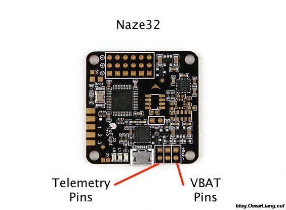
For F1 boards such as the Naze32 FC, you can connect:
- Green wire goes to the Telemetry “+” on the Naze32
- Black wire goes to the “-“ on the Naze32
With all cables connected correctly, Taranis should be ready to receive Telemetry information from the RX. Note that on Naze32, Telemetry will only work when the board is armed.
Betaflight/Cleanflight Configurator Setup
For F3, F4 and F7 FC’s, you will need to configure it in the configurator first.
In the port tab, enable “Frsky” under the telemetry dropdown list for the UART you are using for Telemetry.

And don’t forget to enable “Telemetry” feature in Configuration tab.

Taranis telemetry screens setup
On the radio itself we need to go through the configuration setup in order to:
- display correct voltage information
- alarm on low voltage
- warning on low RSSI signal.
- display additional information (Altitude etc.)
On the Taranis, when we are in the model menu, it takes us to the telemetry screens by holding down the PAGE button. There are three screens and we can customize how the telemetry information is presented and displayed.


In above examples I setup Screen 1 to show numeric values of Total lipo voltage level (Cells), Per Cell and RSSI Signal Strength. (Apart from telemetry, it’s also possible to get RSSI value via a spare PPM Channel)
Screen 2 was setup to show the same values but with a graph (bar chart). It has the low value set to 3.3V and high to 4.10 (which is 100% of the battery voltage). Tmr1 is a timer which is set to 7 minutes, which is my normal average flight time.
Parameters used in telemetry screens are:
- Cells – displays total voltage of the battery
- Cell – displays Cells divided by a number of battery cells.
Voltage level is detected by the Naze32 of the whole LiPo battery, so it is impossible to get voltage of each single cell. Cell value is used for setting voltage alarms on the radio.
Configuration can be done using radio screen or CompanionTX software (available to be downloaded on the OpenTX website), which allows you to upload settings to the radio from your computer. Setting it up directly on the TX takes longer, but you don’t need a computer. Using Companion app is much easier in my opinion, due to the nice and user-friendly interface.


A1 and A2 are the analog telemetry ports on the receiver. On D4R-II we are using A1. First we need to setup the range. The receiver’s maximum input voltage used for telemetry is 3.3V. Internal voltage divider is 4:1. Maximum voltage reading for A1 is 3.3×4=13.2. In my setup I use 13.3V as this is recommended. Detailed video on telemetry voltage calibration can be found here.
Low battery alarms are a matter of personal preferences. In general we don’t want the battery to go completely flat during flight so setting low alarm to 3.5V – 3.7V is sufficient. Use whatever values that you feel should give you enough time to fly back and land safely. Critical alarm means that at this stage, we need to land immediately, otherwise the quadcopter will be likely falling out of the sky due to lack of power.
Taranis telemetry “talking” voice setup
One great feature of the Taranis is the custom voice capability, you get a lovely lady voice talking to you. Taranis radio can return us the information by “talking” to us while we are flying, so we don’t need to look down on the LCD screen. We can configure the radio switches to report battery voltage, or configure it so it warns us when RSSI reaches low or critical level and so on.
My “talking” custom voice setup has three scenarios:
- Taranis tells me when the battery voltage goes down below 3.44V.
- After the board is armed, Taranis reminds me every 60 seconds what the battery voltage is.
- When SH switch is toggled, Taranis tells me the current battery voltage.
In order to do that I set Logical switch L1 with value Cell set to 3.44V. In special functions I have created SF1 that is constantly looking if L1 switch is true to play the sound batlow (battery low).
Created also SF2 to tell me current voltage when switch SH is pressed down. Switch SF3 and SF4 are applying to my timer settings. Switch SF5 speaks voltage value every 60 seconds when arming switch, in my case SF was pressed down to arm the board.


Edit History
- Apr 2015 – guide created
- Aug 2017 – updated how to do this with F3/F4/F7 flight controllers, and updated screenshots for the latest Betaflight configurator GUI
35 comments
Do I need an inverter cable between my D4rII and the Makteksys F405 Wing?
my telemetry doesn’t work . my FC is a F4 FLAME race spec STM32 . i fix the green wire to TX1 on the board but Nothing happen . and i have only 3 sensors : RSSI A1 A2 . i already turn on the telemerty on Betaflight and select frsky telemetry on UART1 in port setting can you help me ??? ps : sorry for my English .. ;) :)
I had Vbat working under Baseflight, using the input FAS on my Taranis 9D+. Cell & Cells read correctly, as did the voltage readout on the model 1st page. When I switched to Betaflight earlier this year (because all my other craft were using Betaflight … my ZMR250 Baseflight racer was my 1st racer, home built .. very old school with 1806 motors, ZTW 12A opto ESCs, Naze32 FC, 3S). In Betaflight, you can monitor VFAS, but not FAS (for Vbat), which I think is the problem.
Hello! One question. I have spf3 board. So I connect frsky pins to tx and ground? And make them softserial ports in cleanflight with frsky telemetry right? Or this is not for analog rssi like d4r-ii has. Do I just connect them and thats it? no Cleanflight settings.
I will update this guide to include F3/F4 flight controller boards, please check back in a day or 2 for the updated tutorial.
Hi Oscar!
It’s incredible that almost every search I made about quads and related stuff your blog always shows up!
I have a simple question… I’m trying to see my battery voltage using a DJI Naza flight controller. Can I plug the green and black wires directly to my battery?
Best regards and congratulations for your blog!
Leonardo Kamache
“Note that Telemetry will only work when the board is armed.”
Oscar Liang , I was going nuts after waiting a month for parts and spending all day wiring up everything. I spent just as much time trying to get telemetry to work searching youtube. Now it works because of your blog. Now I love my Taranis =P
Hi,
Quick question, in the logical switches image, !L1 or L1 ?? Pretty sure it would be L1, but I haven’t had coffee yet.
Cheers,
V
Hi Oscar,
Great basic overview of how to set this up. I like others struggled to follow this guild and get it all working. I just could not get the telemetry outputs/sensors to be detectable. Only the four basic sensors would display, RSSI ALT, A1 & A2. Last night I found a video, which showed the part nobody seems to talk about but in hindsight appears obvious. Here is the correct process, assuming you followed this guide and have it wired correctly and setup in the FC software to output telemetry.
1. Power on the Taranis
2. Power on the FC and connect the flight battery.
3. Arm the FC. (This is the part no one talks about.)
4. Navigate to Telemetry setup on the Taranis, clear all sensors and scan for new ones.
If you don’t arm the motors all you get are the RX’s sensors.
Hi Oscar
Please help, how to connect FrSky D8R-XP telemetry port to flip32 flight controller ?
How to jumper ? How to setup cleanflight ?
( flight controller link: banggood.com/Naze32-Flight-Controller-With-32-bit-STM32-for-Multicopter-10Dof-p-953849.html )
Thank you in advance for your help.
Best regards,
Csaba
Hi Oscar, I absolutely love your How-To’s, they have talked me through MANY parts of my project.
The only thing I am having a REALLY hard time finding, is a How-To to connect the Naze32 Rev6 Full to an X8R. Do you have this walkthrough yet? Is this something you might be able to help with? I know there are many people in my shoes who would benefit from this one…
Hi Oscar
I’m trying to read battery voltage by using FBVS-01 and I just don’t have any success on my Taranis radio. To begin with on my Telemetry screen I dont see any A1 or A2 screen and when I scroll down to screen #1 I can choose Batt on the 1st line and on the secound line I can not find Cells or cell at all. Is just not there. I have updated to latest 2.1.7 and still no luck.
Thanks in advance
Sid
i had it working on all earlier versions except 2.7.1. When going into inputs and editing source there is no option for RSSI. anybody else getting this issue?
Hi Oscar
Please can you refresh screenshots from the new open Tx 2.1?
Screens are diffrent.
Maybe you have found some tutorial in net with new opentx?
thank you
i haven’t updated my Taranis firmware yet… i am not planning to do so because it’s working fine for me and I currently dont have time to do it… sorry!
Oscar,
I had Tx 2.1 firmware installed and had nothing but small issues (here and there). I went back to Tx2.0.19 but now my RSSi is not there anymore (includes Telemetry stuff too). However my Taranis Plus is talking to the Dr4-II fine. I tried re-binding it but still nothing. Any ideas or setting in taranis that I may be missing. My next move is to flash Tx2.0.earlier one.
Thanks,
Is it possible to just solder on the green wire directly to the telemetry pad on the naze32 with out the header pins? I dont want to have to pull out the naze32 completely.
Hi Oscar,
Do you know how to set up telemetry with the Naze32 Rev 6 and an X4R-SB? Thank you!!
no sorry i don’t, i don’t have a rev6 naze32.
Hi Oscar, great and informative work.
I have also a taranis with a frsky d8r-xp receiver on a cc3d board and since I am new to PPM I am struggling to make it work with no success. I jumped pins 3&4 that would get me ppm signal on pin1, how do I connect the RX pin 1 info to the cc3d? only on the signal pins 1,2,8 ? then how do I power the receiver(before when running it on PWM) the three pins powered also the RX… then how in the world can I get the RSSI level display on my Taranis ? this is the reason I bought the xp receiver in the first place ? :( My Taranis is the European version and I use it with an external RF module, what should I choose in the taranis menu: PPM mode ?
The radio binds with the xp rx (dim green led on) but I cannot get any reading in the cc3d interface..
Your support would be appreciated.
Thanks and greetings from Romania :)
Hi Florian
i don’t use CC3D, but from a quick google search, i think pin 1 and 2 on CC3D are the 5V power, and pin 8 is the PPM signal input. Your RX is powered by pin 1 and 2.
When your D8R-XP is in CPPM mode, your Channel 1 is RSSI, you can connect that to your RSSI input on MinimOSD for example.
Without an OSD, the only way to get RSSI is passing it through one of your spare PPM channel.
You don’t need to change anything on the Taranis to use PPM, it’s all done on the RX.
thanks
Oscar
Hi Oscar,
Is it possible to use the Analog Telemetry Port to activate a lost plane buzzer alarm? For example, if I turn the Taranis of and RSSI is zero, can it activate the buzzer? Or on falisafe (when again the TX is off)?
Thanks
Guy
in Cleanflight when you enable Failsafe feature, the buzzer will beep when it detects no RX signal, I think that’s what you are asking?
Hi Oscar,
Thanks for the reply, however, I’m using the D4R with the CPPM so I can’t attach the buzzer to any of the other channels (CH2 is the RSSI and 3&4 are connected with a jumper..), this why I asked about the Analog Telemetry Port..
Thanks
Guy
Thanks for the tutorial.
I have exactly the same setup, but opentx 2.1.1 has others screens.
Telemetry is completly different then the screens you display.
I didnt succeed to setup battery voltage.
Can you place new screens to setup telemetry?
Hi Oscar,
just in addition to Daniel Cruz and for others who may have problems setting up telemetry.
This is buy far the best video which explains how its done when using a BEC.
youtube.com/watch?v=CXWZjqPX_o4
Hi Oscar,
I’m not so sure the Taranis (Open TX) setup part is completely accurate. I see you based it off that YouTube video you link to. However, I read it a bunch of times and I watched the video a bunch of times and what I gather is that the voltage is measured from the BEC if you use A1. I don’t think that’s accurate enough and it certainly doesn’t work for me.
See, for this to work, we’re assuming the BEC’s voltage will change based on the input voltage from the battery pack. However, who’s to say all BEC’s will change in the same fashion. To give you an example, I use a voltage regulator. The one I use is super precise and efficient. It always feeds my Naze32 with 4.95V no matter what the flight pack’s voltage is. I want to also assume some BEC’s will be this precise as well. This would make this method not work because you will always get the same exact reading for your voltage.
I still kept A1 active, simply to monitor my voltage regulator in case it ever fails. However, to actually get a proper voltage reading, there is more to it. For that, I changed the voltage source to “Cells” in Open TX. Then I edited the “Voltage Scale” in Cleanflight, from 110 up. So far, I’ve found 112 gives me the most accurate reading, but I’m still adjusting and I’m off by a few decimals. The other thing I did was select FrSky Auto telemetry in “Ports” on Cleanflight and I inverted the telemetry signal (since apparently it’s inverted for FrSky) in the CLI using “set telemetry_inversion = 1”.
This seems to work well so far. By the way, the video I used to learn this is this one: https://www.youtube.com/watch?v=4AJ7DXftFbI – There are various parts to this video.
Thanks Danny for the heads up! I will look into this and update the post if necessary :)
Thanks. Glad I can help. I’ve kept learning more and there are even more ways to do this. I think the inversion thing is only really needed when using the soft-serial port instead of the telemetry port… but that might also be because my FC already has inversion capabilities built in. Some FCs don’t.
Hi,
I have taranis x9d plus with D4RII . Problem is i cannot get the lipo cell and cells reading from the Taranis since using opto esc and powering the naze32 through UBeC. Already checked wirings ,soldered pin and FC and previously when using BS esc without the UBEC , i can get the lipo reading from Taranis.
Please reply ASAP because i have searched everywhere for the solution. Thanks
Oscar,
I am having issues getting this working. I have a Naze32 Full and D4R-II. I want to use the softserial so I can also run a MinimOSD.
I go into the Ports tab on cleanflight, enable SOFTSERIAL1, check MSP and select Telemetry as FrSky. I connect the greenwire from my D4R-II to PIN 6 on the 10 pin group. I get nothing.
Any suggestions?
Thank you Oscar, I love your articles.
Thank you MG! if there is anything specific you want to know about, we will make it happen!
Hello,
Thank you for this Tutorial.
Is it possible with an CC3D (+ Taranis X9D + D4R II) ?
Sincerely
I think it is, according to the Cleanflight documentation, there is a battery voltage sensor.
From the Open pilot documentation, there are telemetry pins.
however i haven’t done this on a CC3D so i can’t verify this will work as straight forward as the Naze32.